


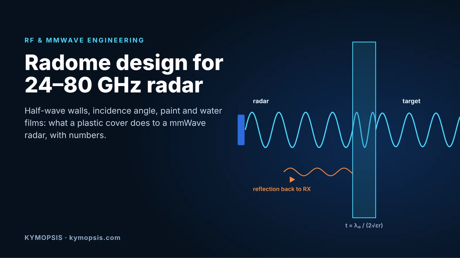
Most radar problems that turn up late in a product are not in the radar. They are in the plastic in front of it. A housing that looked fine on the CAD model detunes the antenna, adds a strong reflection that the receiver sees as a target at zero range, or loses several dB the first time it rains. This article goes through the numbers behind a radome or cover for 24, 60 and 77–81 GHz radar, using a simple transmission-line model that you can reproduce.
The half-wave rule and why it works
A flat dielectric wall in front of an antenna behaves like a short transmission line. Reflections from its front and back faces cancel when the electrical thickness is a multiple of half a wavelength in the material. At normal incidence that thickness is t = n·λ0/(2√εr); for an incidence angle θ it becomes t = n·λ0/(2√(εr − sin²θ)).
| Material (typical εr, tan δ) | First half-wave thickness at 60 GHz | At 77 GHz | Loss at half-wave, 77 GHz |
|---|---|---|---|
| PTFE (2.06, 0.0003) | 1.74 mm | 1.36 mm | ≈ 0.004 dB |
| PP (2.25, 0.0006) | 1.67 mm | 1.30 mm | ≈ 0.01 dB |
| ABS (2.6, 0.007) | 1.55 mm | 1.21 mm | ≈ 0.11 dB |
| PC (2.8, up to ~0.008) | 1.49 mm | 1.16 mm | ≈ 0.12 dB |
The permittivity and loss tangent values are typical figures for unfilled grades. Glass fibre, flame retardants and pigments move them, sometimes a lot, so measure the actual grade and colour before committing a tool.

The chart shows why a cover that “should be transparent” sometimes is not. Between the half-wave points the loss is dominated by reflection, not absorption. A PC wall at three quarters of the half-wave thickness loses about 0.7 dB one way at 77 GHz and reflects with a return loss of only about 9 dB. The radar sees the loss twice, and the reflection arrives at the receiver as a large, near-zero-range echo.
Thin walls
The other classic option is a wall much thinner than a wavelength in the material. That works at lower frequencies: a 0.5 mm PC wall at 24 GHz costs about 0.2 dB one way. At 77 GHz even a 0.2 mm PC wall loses about 0.35 dB with a return loss near 11 dB, and a wall that thin is rarely stiff enough for a housing. Above 60 GHz the half-wave design is usually the practical choice.
Bandwidth and thickness tolerance
A half-wave wall is narrowband in principle, but automotive and industrial radar bands are narrow in relative terms. A PC wall made half-wave at 78.5 GHz still has a return loss of about 25 dB and a loss of about 0.14 dB at 76 and 81 GHz. Thickness tolerance matters more. At 77 GHz a ±0.05 mm error on a 1.16 mm PC wall brings the return loss down to about 23 dB, and ±0.1 mm to about 17 dB. Moulding sink marks, draft angles and ribs behind the radar window all show up here, so the window area should be a uniform, flat section with its thickness controlled on the drawing.
Angle and field of view

The half-wave thickness is correct at one angle only. For a wide field-of-view radar behind a flat cover, the edge of the field sees a different electrical thickness than the boresight. With the 1.16 mm PC wall the TE (perpendicular) return loss falls from 43 dB at normal incidence to about 21 dB at 30° and 13 dB at 45°. TM stays better and passes through the Brewster angle near 59°. For a tilted cover, or a radar that has to see ±60°, design the thickness for the angle that matters most and check the pattern over the full field of view, ideally with the real cover in place.
Mounting distance
Even a good wall reflects a little, and that reflection returns to the antenna with a phase set by the distance between antenna and cover. A change of λ0/4 in spacing, about 1 mm at 77 GHz and 1.25 mm at 60 GHz, moves the round-trip phase by 180°. That can turn a harmless reflection into one that detunes the antenna or raises the TX-to-RX leakage. Treat the antenna-to-cover stack-up as an RF dimension with its own tolerance, not as a mechanical gap.
Paint, colour and coatings
Metallic and pearlescent paints contain conductive flakes and can attenuate a radar signal heavily. Some black pigments, particularly certain carbon blacks, raise the loss tangent of the resin. Chrome-look and vacuum-metallised trims are opaque unless a radar-transparent process is used. If the cover has to match a product colour, ask the resin or paint supplier for a radar-transparent version and measure flat coupons of the real colour and thickness.
Water, ice and dirt
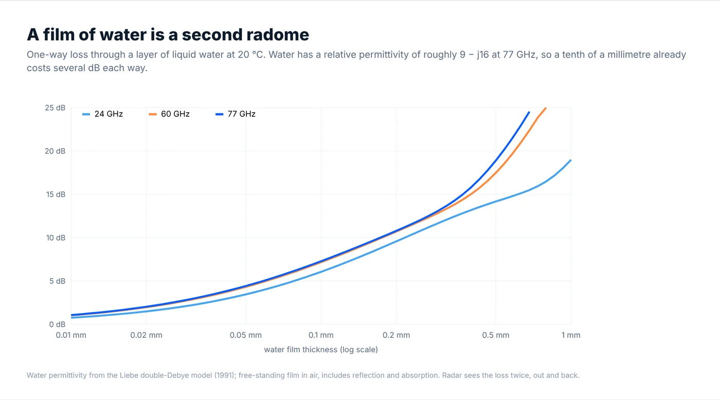
Liquid water at millimetre-wave frequencies has a complex permittivity of roughly 9 − j16 at 77 GHz and about 30 − j35 at 24 GHz. A film only 0.1 mm thick costs about 6 dB one way at 24 GHz and about 7 dB at 60 and 77 GHz, and the radar pays it twice. Beads of water are less harmful than a continuous film, which is why outdoor covers use hydrophobic coatings, slopes that shed water, or heating. In process tanks, condensation and product build-up on the antenna are the equivalent problem. Level radars address them with PTFE or PP lens antennas, flush mounting and air purge connections.
Measuring a cover
The quickest check is a free-space transmission measurement: two horns on a VNA, a calibrated through, then the sample in the beam, at the angles you care about. A flat coupon of the real material, colour and thickness gives εr and tan δ by fitting the slab model above to the measured S21 and S11. The final check is the radar itself, with and without the cover, looking at the near-range leakage, the noise floor and the detection range of a reference target.
Where to go from here
For the radar side, our radar modules and development kits include 60 GHz AiP modules for presence, gesture and vital-sign development and an 80 GHz level radar development kit. All of them end up behind some kind of cover. For measuring materials and covers, our standard gain horns are the starting point for a free-space setup.
If you need a radome or cover designed, simulated or measured for your radar, at these bands or higher, our EM simulation, RF testing and machining services quote per project. A sketch of the stack-up, the band, the field of view and the material are enough to start.
-
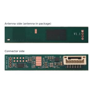
60 GHz AiP Gesture & Presence Radar Module Development Kit (57–64 GHz, 2T2R)
From $19.00DIY boardDevelopment kitReset optionsGesture recognitionPresence, ceiling mountPresence, wall mountSelect options This product has multiple variants. The options may be chosen on the product page -
60 GHz Breathing & Heart-Rate Radar Module Development Kit (Contactless, 1.5 m)
From $19.00Reset optionsDIY boardDevelopment kitSelect options This product has multiple variants. The options may be chosen on the product page -
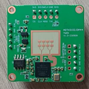
80 GHz Radar Level Sensor Module (76–81 GHz) Development Kit
From $19.00Reset optionsDIY boardDevelopment kitSelect options This product has multiple variants. The options may be chosen on the product page
FAQ
How thick should a polycarbonate radome be at 77 GHz?
For normal incidence, the first half-wave thickness is about 1.16 mm for εr ≈ 2.8. Measure your grade first: a 0.1 mm error already reduces the return loss to about 17 dB.
What is the best radome material for 60 and 77 GHz radar?
Low εr and low loss help: PTFE and PP are the most transparent, PC and ABS are common for housings and work well at half-wave thickness. Avoid metallic paints and test the actual colour.
Why does my radar see a target at zero range after adding a cover?
The cover reflects part of the transmitted signal straight back into the receiver. A wall far from half-wave thickness, or a spacing that puts the reflection in phase at the antenna, makes it worse.
How much does rain affect a 77 GHz radar?
A continuous water film of 0.1 mm costs about 7 dB one way, so about 14 dB on the round trip. Droplets cost less. Hydrophobic coatings, shape and heating are the usual mitigations.
Is a thin-wall radome better than a half-wave radome?
At 24 GHz a thin wall can work well. At 60–80 GHz the wall would have to be a fraction of a millimetre, so half-wave designs are usually more practical.
Method and sources
- Transmission and reflection computed with a single-layer transfer-matrix model in air, including dielectric loss, for TE and TM polarisation. Scripts available on request.
- Water permittivity: H. J. Liebe, G. A. Hufford, T. Manabe, “A model for the complex permittivity of water at frequencies below 1 THz”, International Journal of Infrared and Millimeter Waves, vol. 12, 1991.
- Material values: typical published values for unfilled grades; see J. W. Lamb, “Miscellaneous data on materials for millimetre and submillimetre optics”, International Journal of Infrared and Millimeter Waves, vol. 17, 1996, and the resin supplier’s data for your grade.
- Companion articles: wavelength, machining tolerance and test cost; machined or metallized plastic.