


A standard gain horn, a slotted waveguide array and a 77 GHz radar antenna can all be drawn as the same thing: a metal-walled air channel that ends in a radiating aperture. How that channel is produced decides most of the cost, the achievable band and the batch size. This article compares the routes that are used in practice, with the numbers that decide between them.
If you have not read it, the companion piece on wavelength, machining tolerance and test cost gives the tolerance budget per waveguide band that this article refers to.
Where the seam goes
Almost every waveguide part beyond a straight tube is made from at least two pieces, because a cutter cannot reach the inside of a closed channel. The first design decision is therefore where the joint goes.
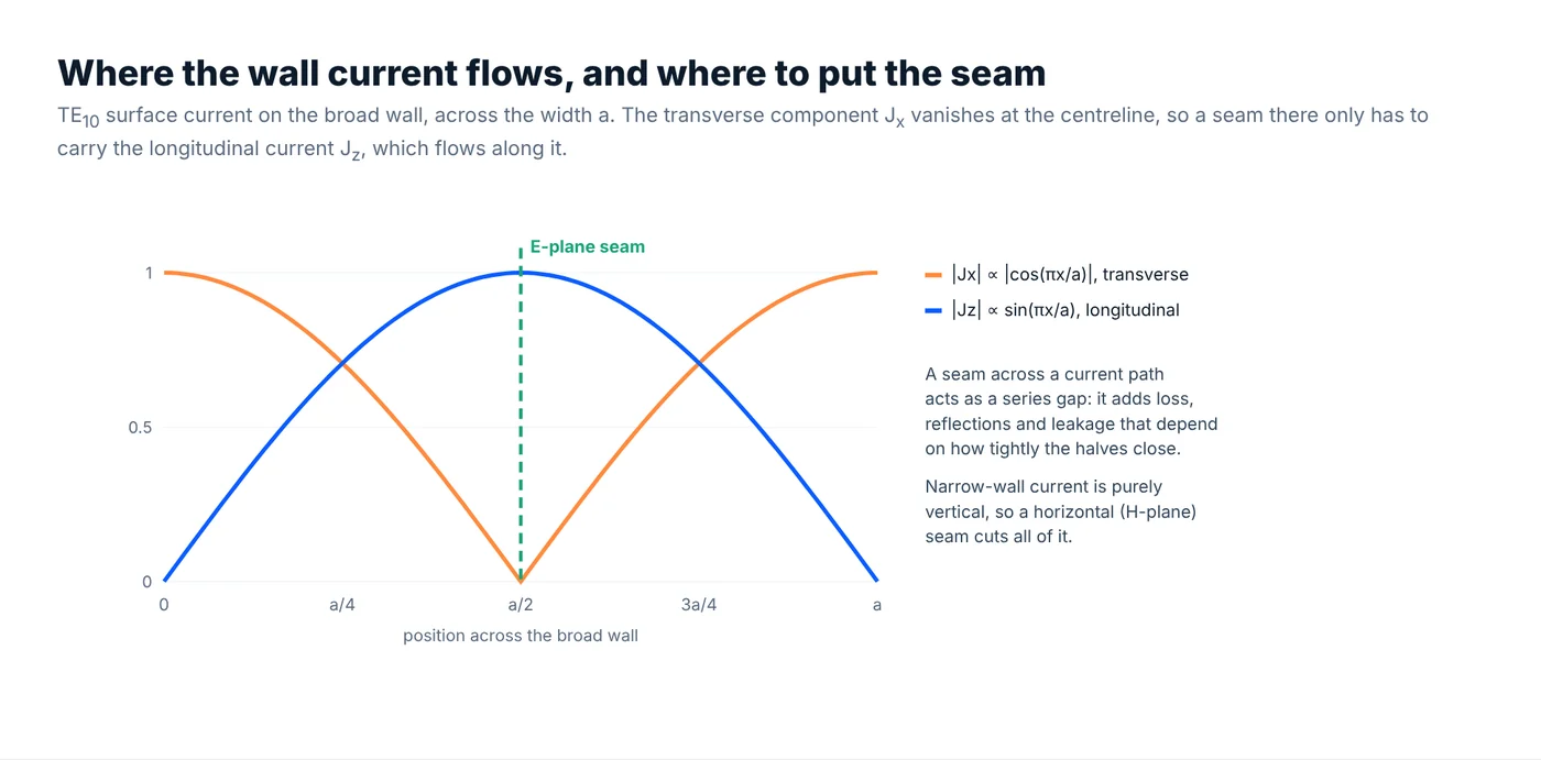
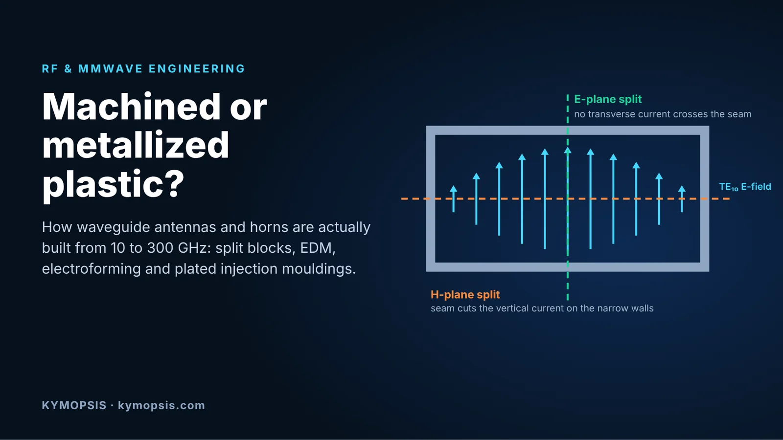
For the TE10 mode, the surface current on the broad wall has a transverse component proportional to cos(πx/a) and a longitudinal component proportional to sin(πx/a). At the centreline the transverse current is zero, which is the same reason a slotted measurement line can run a probe slot along the centre of the broad wall without radiating. A joint in that plane, the E-plane split, only has to carry current that flows along it. Its loss and leakage are therefore relatively insensitive to a small gap between the halves.
The H-plane split runs through the middle of the narrow walls, where the current is entirely vertical. That joint interrupts all of the narrow-wall current, so the contact quality between the halves enters the loss and the return loss directly. It is used only when the geometry forces it, and then usually with brazing, conductive bonding, chokes or a contactless design.
Two practical consequences follow. Split-block parts for the millimetre and sub-millimetre bands are almost always split in the E-plane, with the channel milled half into each block. And when a design has to be split across current, a contactless approach becomes attractive. Gap waveguide, introduced by Kildal and co-workers in 2009, uses a periodic pin or bed-of-nails surface to stop propagation in the gap between two plates, so the parts do not need electrical contact at all. It is used today in some automotive radar antennas and in sub-THz assemblies.
Machining routes
CNC from solid
The default for prototypes and small batches up to roughly W-band. Aluminium 6061-T6 is common because it machines cleanly and is light; brass or copper are used where conductivity or plating behaviour matters. Every internal corner has the radius of the cutter that formed it, so drawings for small apertures should allow corner radii instead of specifying sharp corners that no end mill can produce. A WR-10 channel is 1.27 mm high, which already puts the required tools in the micro-milling range.
Tolerance follows the table in the companion article: general milling holds ±20–25 µm, which is ample at X and Ku band. From V and W band the critical features need precision milling at around ±5–10 µm, with controlled temperature and in-process measurement.
Split-block milling
Two blocks, each carrying half of the channel, pinned and screwed together along an E-plane joint. This is how most WR-10 to WR-1.5 components are built: horns, couplers, filters, mixer and multiplier blocks. Accuracy at the sub-millimetre end is reported at about 2–3 µm from the design values. The alignment of the two halves, the flatness of the mating faces and the screw pattern that clamps them matter as much as the channel itself.
Wire and sinker EDM
Electrical discharge machining cuts sharp internal corners and narrow slots that a cutter cannot reach, which is useful for ridge waveguides, iris filters and septum polarisers. The cost is a recast layer and a surface roughness that is usually worse than a good milled finish, so EDM surfaces in high-band parts are often polished or limited to features where the current density is low.
Electroforming
Copper is grown on a machined mandrel, usually aluminium, which is then dissolved. The internal surface is a replica of the mandrel, so it can be very smooth, and the part has no seam. This makes electroforming a strong choice for corrugated feed horns and small conical horns at millimetre wavelengths, where the internal grooves are hard to machine in one piece. The penalties are long process times, one mandrel per part, and wall thickness and flatness that need a final machining step at the flange.
Die casting and dip brazing
For larger parts at lower bands and in moderate volume, die-cast or dip-brazed aluminium assemblies with finish machining on the flanges and critical faces are common. The casting tolerance is far outside what a millimetre-wave channel can accept, so these processes are mainly used up to K band, or for housings and outer shells that carry machined inserts.
Metallized injection-moulded plastic
Automotive radar at 76–81 GHz changed the economics. A forward-looking radar needs a multi-channel antenna in very large volume, at a price that a milled metal part cannot reach. One answer, developed by several antenna and radar suppliers, is a stack of injection-moulded plastic layers whose channel walls are plated, joined into a 3D waveguide antenna that sits directly on the radar PCB.
The route is: mould the layers in a dimensionally stable resin, activate the surface, deposit a seed layer (electroless copper, or PVD), electroplate copper and often silver, then join the layers by soldering, bonding or a compressed contactless interface. Published examples show that the RF performance can match machined metal in that band. García Tejero et al. report a two-layer metallized plastic slotted array at E-band with more than 13.1 % impedance bandwidth and 90 % (−0.5 dB) total efficiency at 78.5 GHz, and a 3 TX / 4 RX metallized plastic antenna with a compressed waveguide interface to the PCB, 20.1 % bandwidth and up to 94 % total efficiency across 76–81 GHz. A patent family titled “Plated, injection molded, automotive radar waveguide antenna” (US 10,224,617 and continuations) covers the same idea.
Three things make it work, and the same three limit where else it fits:
- Tooling is amortised over volume. A multi-cavity steel mould for precision RF parts is a large fixed cost. It pays off at automotive or telecom volumes, not for a few hundred lab horns.
- Errors are repeatable. Moulded dimensions scatter more than precision-milled ones, but the shrink and warp are systematic and can be compensated in the tool. At 77 GHz a single wall step of about 35 µm between two sections already reflects enough to bring the return loss to 40 dB, which a well-run moulding process with a compensated tool can work within for an array that was designed to be tolerant.
- The plating only has to be a few skin depths thick. Copper’s skin depth at 77 GHz is about 0.24 µm, so electrically a micrometre or two is already a solid wall. Thickness is set instead by adhesion, coverage in deep narrow slots and corrosion resistance.
The risks are mostly mechanical and environmental: plating adhesion through thermal cycling, the difference in thermal expansion between resin and metal, moisture uptake in some resins, and the quality of the joint between layers. For low-volume instrumentation parts, a milled or split-block metal part is still the simpler choice.
Plating finish: the gold-over-nickel trap
A very common finish on connectors and small RF parts is a thin gold flash over an electroless or electrolytic nickel barrier. That is fine for DC contacts. At microwave and millimetre-wave frequencies the current flows in the top fraction of a micrometre, and if the gold is thinner than about one skin depth, much of it flows in the nickel.

With nickel treated as non-magnetic, which is optimistic, a 0.1 µm gold flash over nickel has about 1.85 times the surface resistance of copper at 24 GHz and 1.66 times at 77 GHz. Increasing the gold to 0.5 µm brings it to about 1.2 times copper, the value of solid gold, at both frequencies. Real nickel is ferromagnetic, which raises the penalty for thin gold further. For waveguide interiors and antenna surfaces, either avoid the nickel layer, or specify the gold thickness in micrometres, not as a “flash”.
| Metal | Conductivity (107 S/m) | Skin depth at 77 GHz | Surface resistance vs copper |
|---|---|---|---|
| Silver | 6.17 | 0.23 µm | 0.97× |
| Copper | 5.8 | 0.24 µm | 1.00× |
| Gold | 4.1 | 0.28 µm | 1.19× |
| Aluminium | 3.5 | 0.31 µm | 1.29× |
| Nickel (μr = 1) | 1.43 | 0.48 µm | 2.0× |
Choosing a route
| Route | Typical band | Typical batch | Strengths | Watch out for |
|---|---|---|---|---|
| CNC from solid | 1–110 GHz | 1 – a few hundred | No tooling, fast iteration | Tool radius in corners; tolerance above V band |
| Split-block milling | 30 GHz – 1 THz+ | 1 – a few hundred | Best accuracy for complex mmWave circuits | Half alignment, flatness, clamping pattern |
| EDM features | Any, as an addition | Low | Sharp corners, ridges, thin irises | Recast layer and roughness |
| Electroforming | ~30–300 GHz | 1 – a few hundred | Seamless, smooth interior, corrugations | Lead time, one mandrel per part |
| Die cast / dip brazed + finish machining | 1–26 GHz | Hundreds – thousands | Low unit cost for larger parts | Tolerance only after finish machining |
| Metallized injection-moulded plastic | ~20–100 GHz | Tens of thousands + | Very low unit cost, light, complex 3D channels | Tool cost, plating adhesion, environment |
The bands and batch sizes in the table are typical, not hard limits. A good split-block shop can make a single WR-28 part as easily as a WR-3 one, and some plastic parts are made in lower volumes with 3D-printed and plated cores for prototyping.
Our horns and custom work
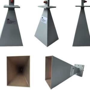
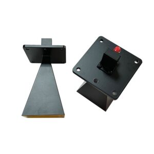
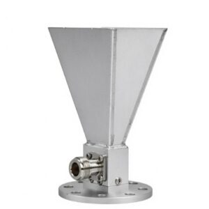
Our horn range is growing toward 60, 77 GHz and higher bands. The machined test and measurement horns listed today include the X-band 20 dB standard gain horn, the K-band 20 dB standard gain horn, a 0.8–10 GHz double-ridged horn and a 6–18 GHz dual-polarised conical horn.
If your band is not listed yet, or you need split-block components, horns to a drawing or a gain target, or a comparison between a machined and a plated-plastic version of the same antenna, our antenna and waveguide machining service quotes each project. A drawing or STEP file, the band, the quantity and the plating requirement are enough to start.
Related: radome design for 24–80 GHz radar.
FAQ
Why are millimetre-wave split blocks split in the E-plane?
At the centreline of the broad wall the transverse TE10 current is zero, so a seam there carries only current flowing along it. Small gaps between the halves then add little loss or leakage. A split through the narrow walls (H-plane) interrupts all of the narrow-wall current.
Can a metallized plastic antenna perform as well as a machined one?
In the 76–81 GHz band, published metallized plastic arrays report 90–94 % total efficiency, comparable with machined metal. The trade-off is tooling cost and environmental qualification, so plastic makes sense at high volume.
How thick should copper plating be at 77 GHz?
Electrically, a few skin depths is enough, and the skin depth of copper at 77 GHz is about 0.24 µm. In practice the thickness is set by adhesion, coverage in deep slots and corrosion, typically a few micrometres.
Is gold-flash over nickel acceptable on a waveguide interior?
Not if loss matters. A 0.1 µm gold flash leaves much of the current in the nickel, about 1.7–1.85 times the surface resistance of copper between 24 and 77 GHz even if the nickel is treated as non-magnetic. Specify about 0.5 µm or more of gold, or a nickel-free finish.
When is electroforming better than machining?
For seamless parts with internal features that are hard to reach with a cutter, such as corrugated feed horns and small conical horns at millimetre wavelengths, in small quantities.
Sources
- P.-S. Kildal, E. Alfonso, A. Valero-Nogueira, E. Rajo-Iglesias, “Local metamaterial-based waveguides in gaps between parallel metal plates”, IEEE Antennas and Wireless Propagation Letters, vol. 8, 2009.
- A. García Tejero et al., “Wideband untilted narrow wall slotted partially staggered waveguide array based on metallized molded plastic at E-band”, IEEE AWPL, vol. 23, no. 3, 2024.
- A. García Tejero, M. Burgos García, F. Merli, “Broadband metallized plastic waveguide antenna with robust isolation interface at 77 GHz”, IEEE AWPL, vol. 23, no. 10, 2024.
- US Patent 10,224,617, “Plated, injection molded, automotive radar waveguide antenna”, and continuations.
- University of Birmingham, CNC-machined WR-1.5 waveguide filter, including CNC accuracy at sub-millimetre wavelengths.
- Surface impedance values computed with the two-layer formula and handbook conductivities; script available on request.