



A GPS antenna with a built-in amplifier needs a few volts, but it only has one coax cable. An SDR or spectrum analyzer input, on the other hand, can be damaged by DC that a radio, an amplifier or an active antenna puts on the same kind of cable. Two small passive parts deal with both cases. A DC block lets RF through and stops DC; a bias tee puts DC onto a coax for a powered device while keeping it away from the receiver. This page explains how both work, what limits them, and how to wire them safely.
What a DC block does
A capacitor passes alternating current and blocks direct current. Put one in series with the centre conductor of a coax and DC on that conductor stops, while an RF signal passes almost untouched. That is all an inner DC block is: a capacitor built into a short SMA body, with the outer conductor connected straight through. Some blocks put the capacitor in the outer conductor too, or only there, to break ground loops; the one we stock is the inner type, so the shields of the two sides stay connected.
Typical uses: in front of a spectrum analyzer, SDR or VNA port when the device under test may carry DC; on the output of a bias tee or amplifier test setup; between two boards whose RF lines sit at different DC levels. If a signal source might carry DC, the block goes in first; our guide to protecting an analyzer input pairs it with an attenuator.
Why there is a lowest frequency
A capacitor’s reactance is 1/(2πfC), so it gets larger as frequency falls. Between a 50 Ω source and a 50 Ω load, a series capacitor forms a high-pass filter whose corner is where its reactance equals the 100 Ω of the two ends together. Below that corner the loss rises 20 dB per decade.
fc = 1 / (2π · 100 Ω · C)

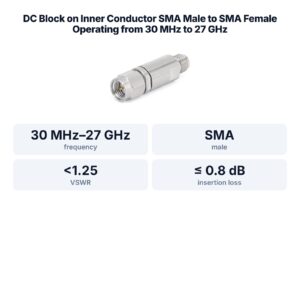
That is why the DC block we stock is specified from 10 MHz, not from zero, and the bias tee’s RF path likewise from 10 MHz; in a bias tee the coil also sets that limit, because its reactance falls at low frequency and it starts to shunt RF into the DC supply. Below the rated frequency the loss rises; for HF or audio work, check the low limit on the datasheet before you add a block. At the top end the limit is set by how well the capacitor and the body hold 50 Ω, which shows up in the VSWR: ≤1.35 for the stocked block over its whole range, a return loss of at least 16.5 dB (see our VSWR and return loss explainer).
The voltage rating matters as much as the frequency. The block we stock is rated for 50 V DC, so a 12 or 24 V line is within it. The datasheet gives no RF power rating, so do not use it to block DC on a transmitter output.
What a bias tee does
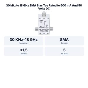
A bias tee has three ports. The RF port has a series capacitor, exactly like a DC block. The combined port carries both RF and DC. The DC terminal connects to the combined port through an inductor, a coil whose impedance is low at DC and high at RF. DC can flow from the terminal out of the combined port, but RF is largely kept out of the DC supply, and DC cannot reach the RF port.
The classic use is powering something at the far end of a cable: an LNA at a receive antenna, an active GPS antenna, a satellite LNB, or an amplifier stage on the bench. The device takes its DC from the centre conductor and sends its RF back down the same cable. Putting the amplifier at the antenna, before the cable loss, is the reason this is worth doing (wiring and supply settings for GPS antennas and LNBs are in powering a GPS antenna, LNA or LNB with a bias tee); our coax loss explainer shows why.
| Line on the datasheet | SMA bias tee we stock | What it limits |
|---|---|---|
| Frequency range | 10 MHz–10 GHz | RF signals outside it see more loss and worse match |
| Insertion loss | < 1.0 dB | RF loss through the capacitor path |
| DC current | 400 mA max | what the coil can carry without overheating or saturating |
| DC voltage | 50 V max | what the capacitor and terminal can stand |
| Operating temperature | −40 to +65 °C | where the ratings apply |
Wiring safely
- Know which port carries DC: the combined RF+DC port and the DC terminal. The RF-only port is blocked. Check the marking on the housing before connecting.
- Never feed DC into something that is a short or a resistor at DC: a 50 Ω termination, an attenuator, a passive loop or folded-dipole antenna, or a DC-coupled instrument input. The supply then drives current straight into it.
- Never connect the combined port straight to an instrument input. If anything after it might be connected to a receiver or analyzer, add a DC block.
- Use a current-limited supply set just above what the powered device needs, well under the bias tee’s rating, so a short in a cable or connector does not burn anything.
- Check the voltage the far-end device expects. Many active GPS antennas and LNBs have specific supply ranges printed on their own datasheet.
- Connect RF first, then turn on DC; turn DC off before disconnecting, so the centre pins do not spark or short. Even through a DC block, switching DC on or off sends a short spike through the capacitor, so keep sensitive inputs disconnected or padded while you switch.
FAQ
What is the difference between a DC block and a bias tee?
A DC block only stops DC. A bias tee also has a DC terminal and a coil, so it can feed DC onto the coax while keeping it off the RF port.
Does a DC block work at low frequency?
Only down to its rated limit. A series capacitor is a high-pass filter; the one we stock is specified from 10 MHz. Below that it still passes signal, with more loss and worse match.
Can I power a GPS antenna with a bias tee?
Yes, if the antenna takes power over its coax and its supply voltage and current are within the bias tee’s rating (50 V, 400 mA for the one we stock); its 10 MHz–10 GHz range covers the GPS bands.
Do I need a DC block if I already use a bias tee?
The bias tee’s RF port is already blocked. Add a separate DC block where DC could reach an instrument by another path, for example when the combined port is reconnected.
Can a DC block go on a transmitter output?
Not the one we stock: its datasheet gives no RF power rating, and the same applies to the bias tee. Use a part rated for the power.
Sources and method
- Supplier datasheet for the SMA DC block we stock: 0.01–18 GHz, insertion loss ≤0.7 dB, VSWR ≤1.35, 50 V DC.
- Supplier product data for the SMA bias tee we stock: 10 MHz–10 GHz (we quote the narrower of the two ranges the supplier lists), insertion loss <1.0 dB, 400 mA, 50 V, −40 to +65 °C.
- D. M. Pozar, Microwave Engineering, 4th ed., Wiley, 2012: reactance, two-port networks.
The high-pass curve is computed for an ideal capacitor; product figures are from the supplier data.