


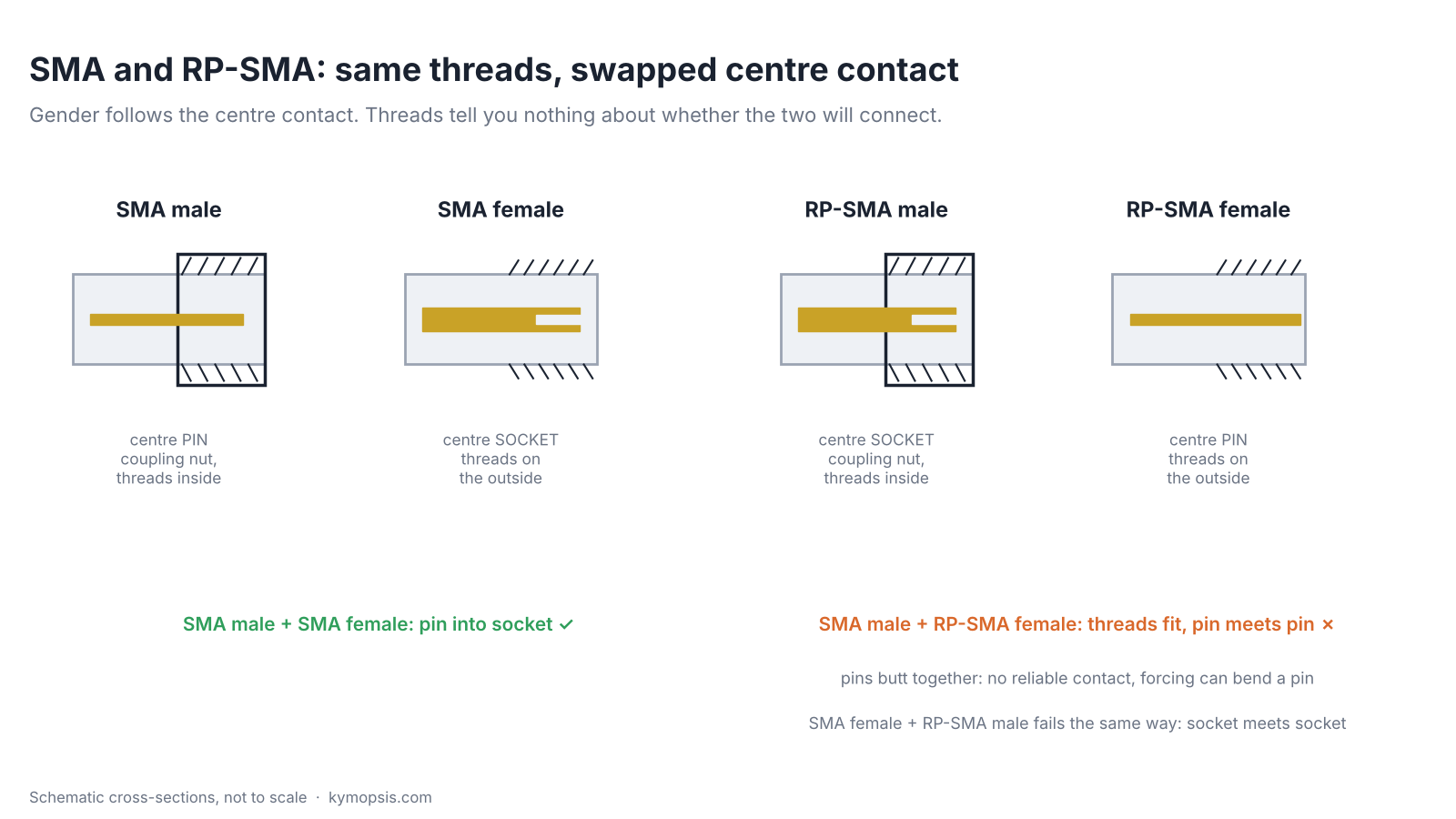
An SMA connector that screws on smoothly can still carry no signal at all. RP-SMA, the reverse-polarity version used on many Wi-Fi routers and antennas, has the same thread as SMA but swaps the centre pin and socket. Screw an SMA male onto an RP-SMA female and the nut tightens, the two centre pins butt together, contact is absent or unreliable, and tightening further can bend a pin. Gender is set by the centre contact, not the thread: a pin is male, a socket is female. With that rule and the rated frequency range of each adapter, picking the right adapter between SMA, RP-SMA, BNC, N and UHF gear becomes a lookup, not a guess.
Pin or socket decides the gender
On every coaxial connector family the coupling and the contact are separate parts. The coupling (a nut, a bayonet, a threaded body) holds the two halves together; the centre contact carries the signal. Naming follows the contact: a centre pin is male, a centre socket is female. For SMA the male also carries the coupling nut with the thread inside, and the female has the thread on the outside of its body. RP-SMA keeps those threads and swaps only the contact, so an RP-SMA male has the nut and a socket, and an RP-SMA female has the outer thread and a pin.
That gives two failure cases. SMA male on RP-SMA female: pin meets pin, no contact. SMA female on RP-SMA male: socket meets socket, no contact. The nut will usually start on the thread, but in the pin-to-pin case the two pins butt together and forcing the nut can bend them. If a mating feels stiff, stop and look into the centre. The symptom is a link that does nothing or a sweep that looks like an open circuit. If a router antenna shows nothing on an SMA analyzer, look into the connectors before blaming the antenna; the ESP32 external antenna guide walks through the same trap on a module. We do not stock RP-SMA adapters at the moment; if you need one, the rule above tells you which: the side facing the router or antenna must have the opposite contact to it.
The families you will meet
| Connector | Coupling | Where you meet it | Notes |
|---|---|---|---|
| SMA | screw, small | RF modules, SDRs, VNAs, test gear, radar boards | the default for small RF hardware |
| RP-SMA | screw, same thread as SMA | Wi-Fi routers and their antennas | swapped centre contact, see above |
| BNC | bayonet, quarter turn | oscilloscopes, older test gear, video | 50 Ω and 75 Ω versions exist |
| N | screw, large | antennas, outdoor and higher-power gear | weatherproof versions are common |
| UHF (SO-239 / PL-259) | screw, large | HF and VHF amateur radio | not a constant-impedance design; keep it to the low bands |
Adapters join these families with a short 50 Ω section. Each adapter has its own rated frequency range, set by the more limited of its two interfaces and the transition between them, and that range is printed on the datasheet, not implied by the connector names.
Rated range and loss of each adapter
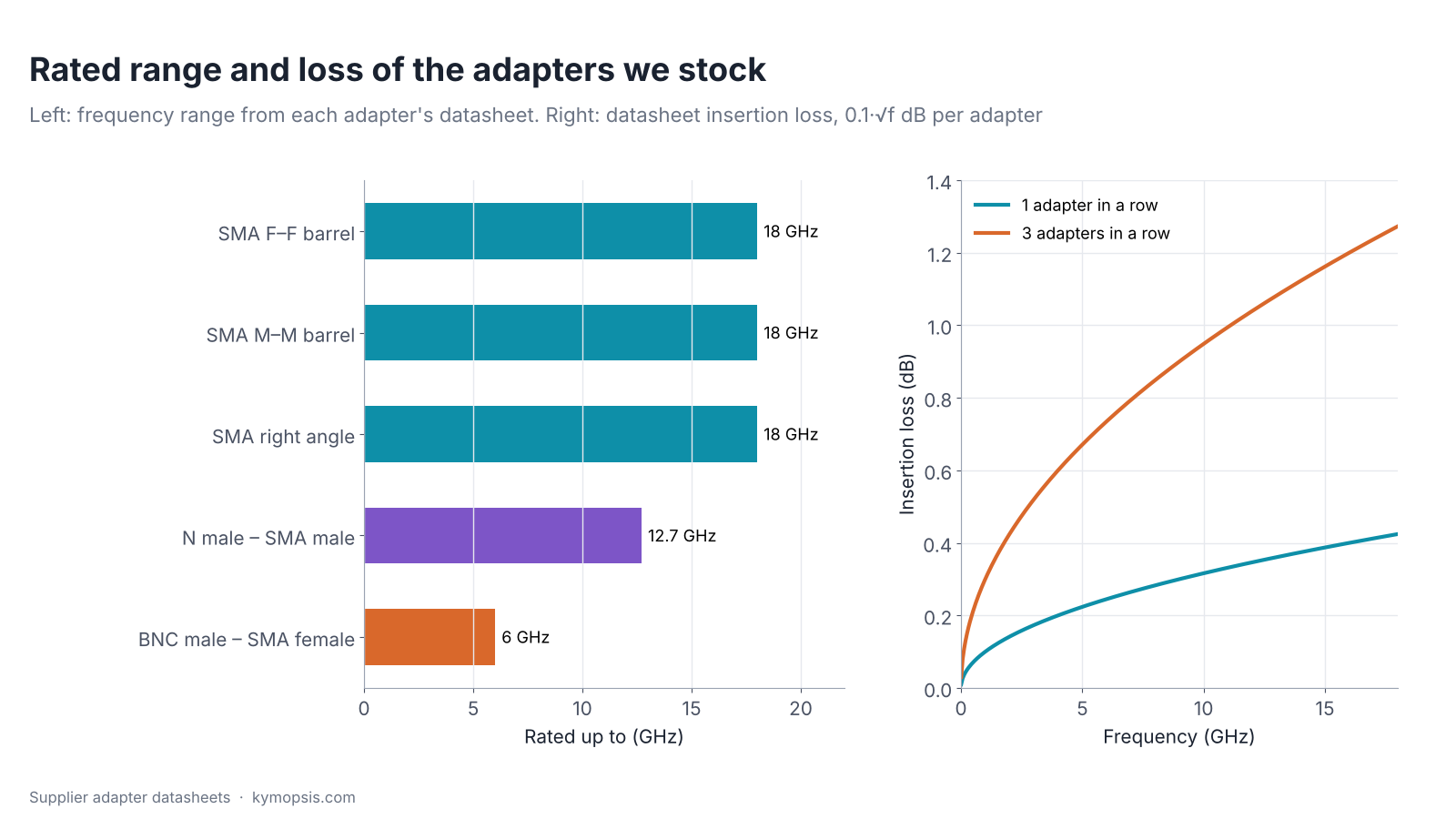
The datasheets for the adapters we stock give the insertion loss as 0.1·√f dB with f in GHz: 0.10 dB at 1 GHz and 0.24 dB at 6 GHz for one adapter. That is small, but it adds up: three adapters in a row at 6 GHz cost 0.73 dB, and each one also adds a small reflection (VSWR ≤1.15 for the male–male barrel and ≤1.25 for the female–female barrel, both to 18 GHz; ≤1.25 to 8 GHz for the right angle; ≤1.30 for the BNC adapter). On a VNA, put the adapters you need before the calibration plane so the calibration removes them; our NanoVNA accessories guide shows where that plane goes.
The BNC adapter’s 6 GHz rating is the limit to watch. With this adapter, BNC gear is fine for oscilloscope probes, HF and VHF, and sub-6 GHz Wi-Fi and ISM work (other BNC parts may be rated lower, so check the rating of yours); above that, move the measurement to SMA or N connectors.
50 Ω and 75 Ω do not mix well
BNC and F connectors also come in 75 Ω versions for video and TV. A 75 Ω part in a 50 Ω line is a step in impedance: the reflection coefficient is (75−50)/(75+50) = 0.2, a return loss of 14 dB, VSWR 1.5, and 0.18 dB of the power does not get through. That is for one junction. A short 75 Ω adapter has two, so its reflection varies with frequency from near zero up to about 8 dB return loss. That is acceptable for a quick check, not for measuring an antenna match, where the adapter’s own 14 dB return loss would hide anything better. All the adapters we sell are 50 Ω.
Γ = (Z2 − Z1) / (Z2 + Z1), RL = −20·log10|Γ|
Look after the threads
- Turn the nut, not the body. Rotating the centre pin inside the socket wears both.
- Finger-tight is enough for most bench work. For repeatable measurements use an SMA torque wrench set to the torque the connector maker specifies. Never tighten further with pliers.
- Leave a good-quality adapter on each instrument port as a connector saver; it takes the wear.
- Keep dust caps on unused ports and check the centre pin for bends before mating.
Which adapters to keep
| You have | You need to reach | Adapter |
|---|---|---|
| SMA cable or instrument | another SMA cable | SMA female–female barrel |
| two SMA female ports | connect them directly | SMA male–male barrel |
| SMA port, tight space | a cable at 90° | SMA right-angle adapter |
| SMA cable | a BNC jack on a scope or radio | BNC male–SMA female (to 6 GHz) |
| SMA cable or port | an N jack on an antenna or amplifier | N male–SMA male (to 12.7 GHz) |
-

SMA Male to SMA Female Straight Adapter, DC–18 GHz
$8.00 Buy Now -
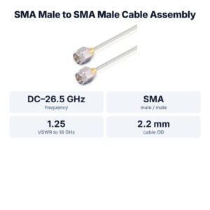
SMA Male to SMA Male Cable Assembly, .086″ Semi-Flexible Coax Cable Without FEP Jacket, DC–26.5 GHz
From $42.00Reset options100 mm150 mm200 mm250 mm300 mm400 mm500 mm800 mm1000 mmSelect options This product has multiple variants. The options may be chosen on the product page -
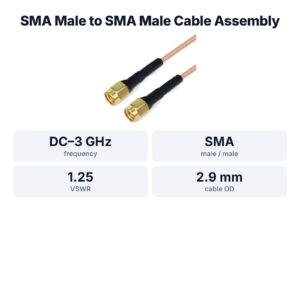
SMA Male to SMA Male Cable Assembly, RG316 Series Flexible Coax Cable, DC–3 GHz
From $22.00Reset options200 mm300 mm500 mm800 mm1000 mm1200 mm1500 mm2000 mmSelect options This product has multiple variants. The options may be chosen on the product page
FAQ
How do I tell SMA from RP-SMA?
Look into the centre. An SMA male (nut with internal thread) has a pin; an RP-SMA male (same nut) has a socket. An SMA female (external thread) has a socket; an RP-SMA female has a pin.
Will an SMA cable work on a Wi-Fi router?
Only with the right adapter if the router uses RP-SMA. The thread fits either way, but without matching centre contacts no signal passes.
Is BNC good enough for 2.4 GHz?
The BNC male to SMA female adapter we stock is rated to 6 GHz, so 2.4 GHz is inside its range. Expect slightly more reflection than an all-SMA path.
Can I use a 75 Ω BNC adapter in a 50 Ω system?
It works, but each 50/75 Ω junction reflects at 14 dB return loss (VSWR 1.5), and the two junctions together can be worse. Avoid it whenever you measure match or need accurate levels.
Sources and method
- Supplier adapter datasheets: SMA female–female, male–male and right-angle (DC–18 GHz), N male–SMA male (DC–12.7 GHz), BNC male–SMA female (DC–6 GHz); insertion loss 0.1·√f dB; VSWR as quoted.
- D. M. Pozar, Microwave Engineering, 4th ed., Wiley, 2012: reflection coefficient, return loss and mismatch loss.
- ARRL Handbook for Radio Communications (coaxial connector families and their typical uses).
Loss and mismatch figures are computed from the datasheet formula and the reflection-coefficient formula shown; nothing here is a measurement.