



Open up a 77 GHz radar test setup and the RF does not travel in cables at all, but in small rectangular metal tubes bolted together with round, pinned flanges. At millimetre-wave frequencies, waveguide carries signals with less loss than any practical coax and fits directly onto horn antennas. A waveguide is a hollow metal pipe that carries a wave only above a cutoff frequency set by its width: c/(2a) for the usual TE10 mode. This page explains cutoff, the TE10 mode, what the WR numbers mean, why the wave inside is longer than in free space, and how to handle waveguide parts.
Why use a pipe instead of a cable
A coax carries a wave between a centre conductor and a shield. As frequency rises, two things go wrong. Loss grows roughly with √f (our coax loss explainer shows this from datasheet values), and the cable has to get thinner, because a coax also has an upper limit where higher-order modes start to propagate and the clean single-mode behaviour ends. Thinner cable means a thinner centre conductor and still more loss.
A waveguide drops the centre conductor. The wave bounces between the walls of a hollow pipe, the currents spread over a much larger metal surface, and there is no dielectric to heat. That makes waveguide the low-loss, high-power choice at millimetre-wave frequencies. The cost is that a waveguide only works over a limited band, and it does not pass DC or anything below its cutoff.
Cutoff and the TE10 mode
A wave can only travel down the pipe if it fits across it. In the simplest pattern, called TE10, the electric field runs between the two broad walls, is strongest in the middle and falls to zero at the narrow side walls: exactly half a wavelength across the width a. The lowest frequency where that half-wave fits is the cutoff:
fc = c / (2a)
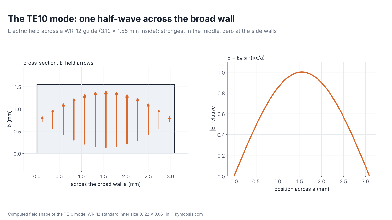
Below cutoff the field does not travel; it dies away within a short distance. At twice the TE10 cutoff the next pattern, TE20 (a full wave across a), can start; in standard guides, whose width is twice their height, TE01 starts at the same frequency. Between the two, only TE10 travels, which is what you want: one mode, one predictable behaviour. Standard bands sit at about 1.25 to 1.9 times the cutoff, staying clear of the steep region near cutoff and of the next mode.
| Size | Inner a × b | TE10 cutoff | Horn band (supplier) | Band / cutoff |
|---|---|---|---|---|
| WR-15 | 0.148 × 0.074 in (3.76 × 1.88 mm) | 39.9 GHz | 50–75 GHz | 1.25–1.88 |
| WR-12 | 0.122 × 0.061 in (3.10 × 1.55 mm) | 48.4 GHz | 60–90 GHz | 1.24–1.86 |
| WR-10 | 0.100 × 0.050 in (2.54 × 1.27 mm) | 59.0 GHz | 75–110 GHz | 1.27–1.86 |
The WR number is the inner broad-wall width in hundredths of an inch, so WR-12 is 0.122 in wide. The band column is the frequency range of the horn antenna the supplier makes for each size, which follows the standard bands. The 57–64 GHz radar band lies inside the WR-15 band and only partly inside WR-12 (from 60 GHz); 76–81 GHz radar lies inside both the WR-12 and WR-10 bands.
The wave inside is longer
Inside the guide the wave zig-zags between the walls, so along the guide its pattern repeats over a longer distance than in free space. That guide wavelength depends strongly on frequency, especially near cutoff:
λg = λ0 / √(1 − (fc/f)²)
At 77 GHz the free-space wavelength is 3.89 mm, but in WR-12 it is 5.00 mm. This matters for anything sized in wavelengths inside a guide, such as a quarter-wave short or the spacing of slots, and it means a signal’s phase through a length of waveguide changes faster with frequency than through coax. The energy itself travels more slowly than light (the group velocity), which also follows from the zig-zag.
Flanges and handling
- Waveguide parts join at flanges with alignment pins and screws. The horn datasheets name the flange: UG-385/U for WR-15 and UG-387/U for WR-12 and UG-387/U (modified) for WR-10.
- Align on the pins before tightening, and tighten the screws evenly; a gap or a step at the joint reflects and leaks.
- Keep the inside clean and dry and the flange faces unscratched; at these sizes a burr, a dent or a fleck of dust at the joint causes a measurable mismatch. Do not overtighten, use matching flange types on both sides, and rotate the guides so their polarization lines up.
- Radar chips in this range usually feed antennas printed on the board or built into the package; test instruments and frequency extenders bring their RF out on a waveguide flange. Going to or from coax needs a waveguide-to-coax transition with a millimetre-wave coax connector; SMA is not used this high.
Where you meet it: horn antennas and mmWave radar
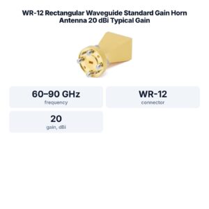
The most common waveguide part on a radar bench is a horn antenna: a waveguide that flares out into a funnel, turning the guided wave into a beam. Its gain depends on the size of the opening in wavelengths. The WR-12 standard gain horn we stock covers 60–90 GHz with 20 or 25 dBi and a VSWR of 1.1 at most, which makes it a reference antenna for 60–64 GHz and 76–81 GHz radar measurements. Below the waveguide range, a K-band horn with an SMA connector covers 18–26 GHz.

FAQ
What is waveguide cutoff frequency?
The lowest frequency a waveguide carries in a given mode. For the usual TE10 mode it is c/(2a), with a the inner broad-wall width: 48.4 GHz for WR-12.
What does WR-12 mean?
Waveguide, rectangular, with an inner broad-wall width of 0.12 inches (0.122 in, 3.10 mm). Its standard band is 60–90 GHz.
Why not use coax at 77 GHz?
Coax does exist at 77 GHz, but it must be very small, so it is costly and lossy per metre. Waveguide has no centre conductor and loses less, at the price of a limited band.
Can waveguide carry DC or low frequencies?
No. Nothing below the cutoff travels down the guide.
Why is the wavelength inside a waveguide longer?
The wave zig-zags between the walls, so its pattern along the guide repeats over a longer distance: λg = λ0/√(1 − (fc/f)²).
Sources and method
- Supplier horn antenna datasheets: WR-15 50–75 GHz (UG-385/U flange), WR-12 60–90 GHz 20 and 25 dBi, VSWR ≤1.1 (UG-387/U), WR-10 75–110 GHz (UG-387/U, modified), K-band 18–26 GHz SMA female.
- EIA standard rectangular waveguide inner dimensions (WR-15 0.148 × 0.074 in, WR-12 0.122 × 0.061 in, WR-10 0.100 × 0.050 in).
- D. M. Pozar, Microwave Engineering, 4th ed., Wiley, 2012: rectangular waveguide modes, cutoff, guide wavelength.
Cutoff, guide wavelength and field shapes are computed from the standard dimensions; band limits are from the supplier datasheets.