


A wideband SDR’s front end sees everything from a few megahertz to a few gigahertz at once, even though it only processes a few megahertz of it, and that is also its weakness. A strong FM broadcast station, a nearby pager transmitter or a phone tower can push the receiver’s front end into overload, and the result is spurious signals all over the band you actually care about. A filter in front of the SDR removes the signals you do not want before they reach the first amplifier. This page covers the four filter shapes, why SDRs need them, how to read a filter datasheet, and where the filter goes in the chain.
Four filter shapes
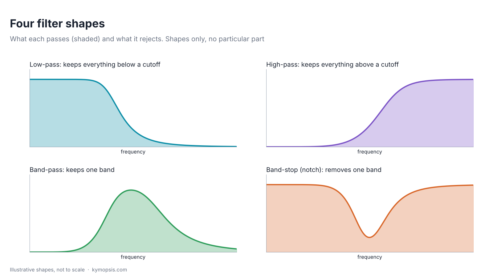
- Low-pass keeps everything below a cutoff. Used for HF reception, against aliasing in direct-sampling receivers, and to remove harmonics after a transmitter.
- High-pass keeps everything above a cutoff, for example to keep strong AM broadcast and HF signals out of a VHF/UHF receiver.
- Band-pass keeps one band and rejects both sides. The cleanest option when you only listen to one band.
- Band-stop (notch) removes one band and keeps the rest; the classic SDR case is an FM broadcast stop filter for 88–108 MHz.
Why an SDR needs a filter
Three things go wrong without one.
Overload. The receiver’s amplifier and analog-to-digital converter have a limited range. One very strong signal anywhere inside the input bandwidth uses up that range; weak signals are lost, and mixing between strong signals creates intermodulation products that look like real stations. Removing the strong signal before the amplifier fixes this; turning the gain down only trades one problem for another.
Spurious responses. Mixer-based receivers can also respond at image and harmonic frequencies that have nothing to do with where they are tuned. A filter that passes only the wanted band removes those inputs.
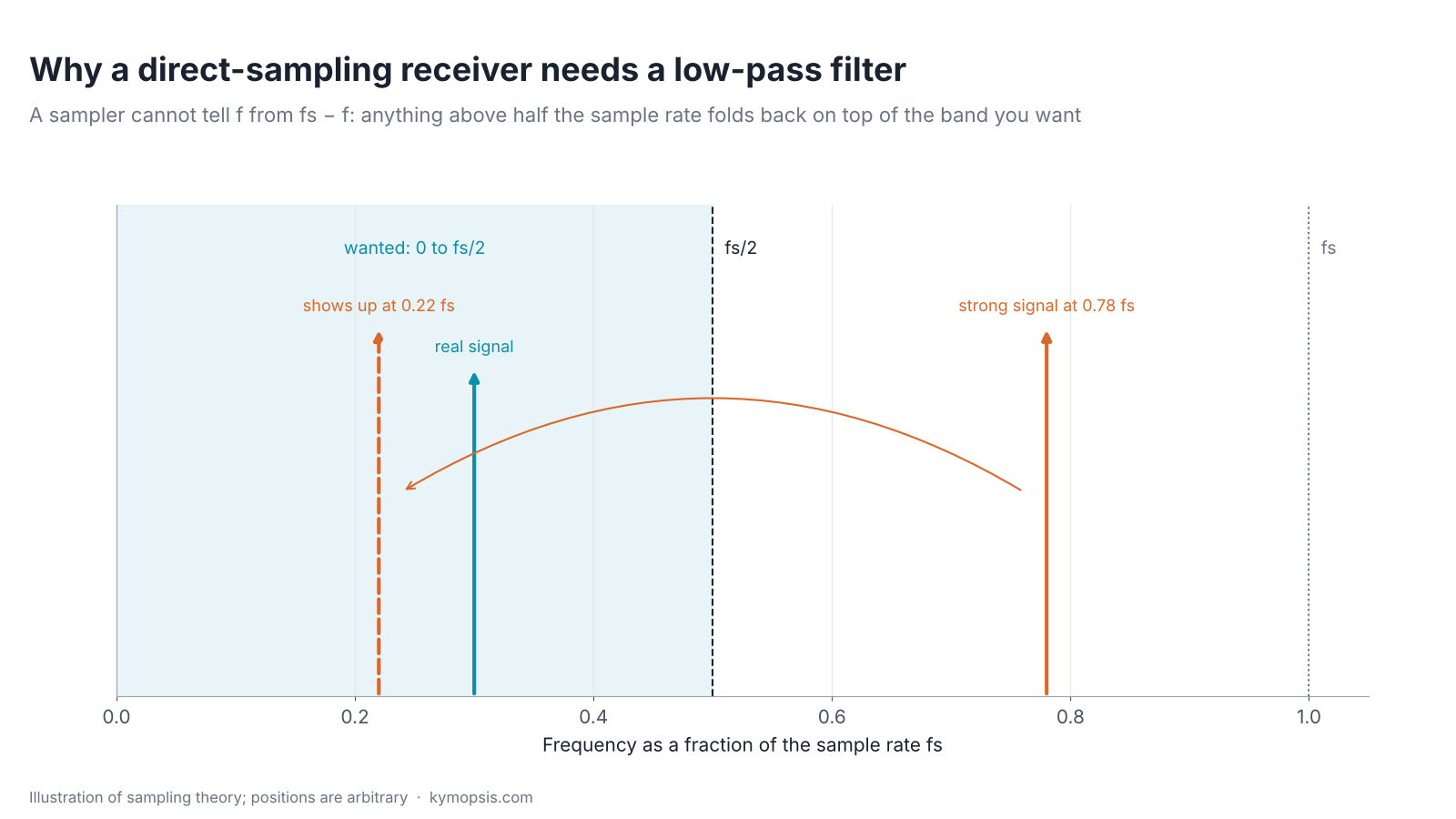
Aliasing. A receiver that samples the antenna signal directly cannot tell a signal at f from one at fs − f, where fs is the sample rate. Anything above half the sample rate folds back on top of the band you want. The cure is a filter in front of the converter that rejects everything outside the wanted Nyquist zone, normally a low-pass that is well down by fs/2. Once folded, the two signals cannot be separated.
On transmit the problem runs the other way: a small SDR transmitter puts out harmonics at multiples of the wanted frequency. A low-pass filter after it, with a cutoff above the wanted frequency and below the second harmonic, keeps those off the antenna. Check where the filter’s guaranteed rejection starts: the one we stock is specified only from 150 MHz, and its datasheet gives no power rating, so it is for low-power SDR outputs only.
Reading a filter datasheet
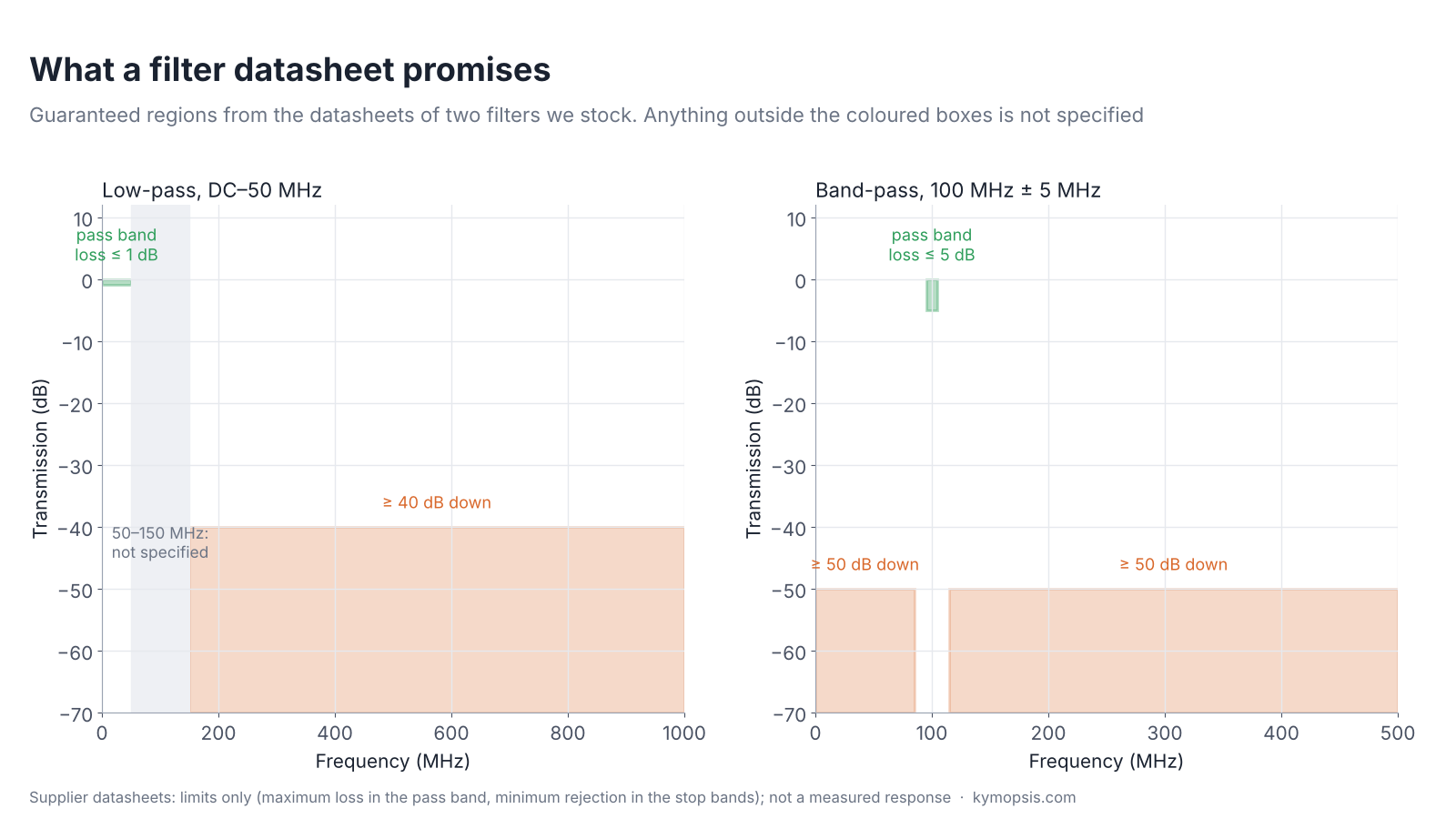
A filter datasheet gives limits for regions, not a curve. Take the two filters we stock:
| Line | Low-pass DC–50 MHz | Band-pass 100 MHz ± 5 MHz | What it means |
|---|---|---|---|
| Pass band | DC–50 MHz | 95–105 MHz | where the loss limit applies |
| Insertion loss | ≤ 1 dB | ≤ 5 dB | worst-case loss for the signal you want |
| Rejection | 40 dB at 150–1000 MHz | > 50 dB at DC–85 and 115–500 MHz | minimum loss for what you want removed |
| VSWR | ≤ 1.5 | ≤ 1.5 | match in the pass band; see our VSWR explainer |
| Connectors | SMA female | SMA female | add SMA male cables or adapters |
The gaps matter. The low-pass filter’s datasheet gives no figure between 50 and 150 MHz, so it does not promise anything about the FM broadcast band at 88–108 MHz; do not buy it as an FM filter. It is a good fit for HF reception and other work below 50 MHz where VHF and UHF signals must be kept out; the 6 m band (50–54 MHz) lies above its specified pass band, and nothing is specified above 1 GHz. The band-pass filter sits on 95–105 MHz and rejects everything from DC to 85 MHz and from 115 to 500 MHz by more than 50 dB; above 500 MHz nothing is specified. It suits receiving part of the FM broadcast band, not rejecting it. Its up-to-5 dB pass-band loss is the price of a narrow band. The VSWR line means the same as for any other part; our VSWR and return loss explainer converts it.
Where the filter goes
Before the first amplifier, a filter protects that amplifier from overload, but its loss adds to the system noise figure dB for dB, exactly like cable loss (see our coax loss explainer). After a low-noise amplifier, the filter’s loss hardly matters, but the amplifier itself sees every strong signal. The usual answer: if strong out-of-band signals are the problem, filter first and accept the loss; if the band is quiet and signals are weak, put the amplifier first. When an LNA is powered over the coax, check that the filter passes DC if it sits between the bias tee and the LNA; a band-pass or high-pass filter usually blocks DC, and some short it to ground, which can overload the bias supply. The low-pass we stock is specified from DC, but its datasheet gives no DC current rating.
For measuring a transmitter, a filter is not a replacement for an attenuator: the wanted signal passes it with only the pass-band loss. Protect the instrument input with a pad as described in our analyzer protection guide.
B2B engineering · KymopsisNeed a filter we do not list?FM band-stop, ADS-B, GPS, ISM band-pass and custom cutoffs to order. Send the pass band, the band to reject and the connectors.FAQ
Do I need a filter for my SDR?
If strong signals nearby cause spurious stations or overload, yes. A band-pass for the band you use, or a band-stop for the strong signal, is the usual fix.
Will a 50 MHz low-pass filter remove FM broadcast?
The one we stock is not specified between 50 and 150 MHz, so it does not promise to. Its guaranteed rejection starts at 150 MHz.
Does a filter lose signal?
Yes, its insertion loss: at most 1 dB for the low-pass and at most 5 dB for the band-pass we stock, inside their pass bands.
Filter before or after the LNA?
Before, when strong signals overload the LNA; after, when signals are weak and the band is quiet. Loss before the LNA adds to the noise figure.
Why does a direct-sampling receiver need a low-pass filter?
Signals above half the sample rate fold back into the wanted band and cannot be removed afterwards.
Sources and method
- Supplier datasheets for the filters we stock: SMA low-pass DC–50 MHz (VSWR ≤1.5, insertion loss ≤1 dB, rejection 40 dB at 150–1000 MHz); SMA band-pass 100 MHz, ±5 MHz (VSWR ≤1.5, insertion loss ≤5.0 dB, rejection >50 dB at DC–85 MHz and 115–500 MHz).
- D. M. Pozar, Microwave Engineering, 4th ed., Wiley, 2012: filter types, insertion loss, noise figure of lossy networks.
- H. Nyquist and C. E. Shannon: sampling theorem (aliasing).
Datasheet limits are drawn as given; filter shapes and the aliasing diagram are illustrations. Nothing here is a measurement.