

Engineering Notes
Practical RF and radar design notes: radomes, waveguides, antennas, cables and machining, with the numbers behind each choice.
Read a series
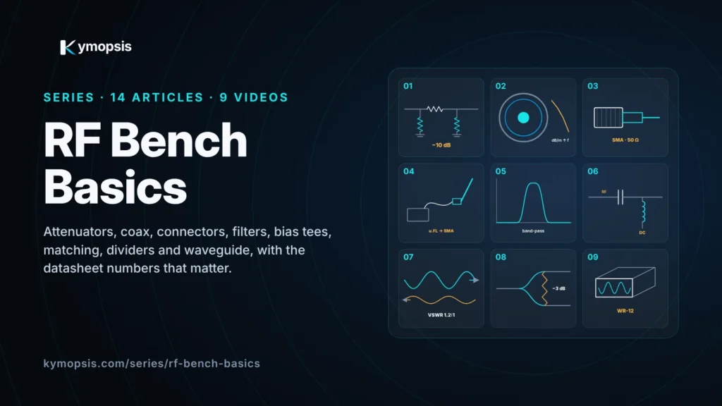
Series · 14 chapters · 4 partsRF Bench BasicsHands-on RF for the bench: attenuators, coax loss, connectors, filters, DC blocks and bias tees, 50 ohm matching, power dividers and waveguide, each with the datasheet numbers that matter and a short video.Start with Chapter 1 →Series page →
All 14 chapters
Part A · Levels, cables and connectors
- 1RF Attenuators Explained: dB, Pi and T Pads, and Return Loss
- 2Coax Cable Loss vs Frequency: What Your SDR Cable Costs You
- 3SMA vs RP-SMA vs BNC vs N: Choosing the Right RF Adapter
- 4ESP32 External Antenna: U.FL to SMA Done Right
Part B · Filters, DC and matching
- 5SDR Filters Explained: Low-Pass, Band-Pass and Band-Stop
- 6DC Block and Bias Tee Explained: DC and RF on One Coax
- 750 Ohm, VSWR and Return Loss Explained (and What a Load Does)
- 8RF Power Dividers and Combiners Explained: How a Wilkinson Works
Part C · Waveguide and mmWave parts
- 9Waveguide Explained: Cutoff Frequency, TE10 and WR Sizes
- 10Machined or Metallized Plastic? How Waveguide Antennas and Horns Are Built, 10 to 300 GHz
- 11Wavelength, Machining Tolerance and Test Cost: Why mmWave Parts Get Expensive