


A pocket vector network analyzer such as the NanoVNA arrives with a calibration kit and a couple of short cables, and that is enough to sweep an antenna on the bench. The trouble starts on the second project: the antenna has a different connector, the cable has to reach a mast, an amplifier needs measuring. Three things decide whether your readings stay trustworthy: where you calibrate, whether your test cables hold their shape, and whether anything strong enough to hurt the ports can reach them. The accessories worth buying follow from those three, and they are fewer than most kit lists suggest.
Calibrate at the end of the cable you measure with
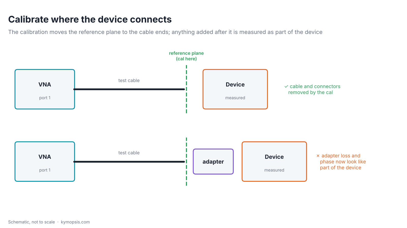
A VNA calibration (open, short, load, and thru for two-port work) measures known standards and works out everything between the analyzer’s internal bridge and the point where the standards were attached. That point is the reference plane. Whatever lies before it, the cable, its connectors, a barrel, is removed from the result. Whatever you add after it is not: it shows up as loss, phase and mismatch of the device.
So the rule is simple: decide the full chain first (cable, adapters, the connector type of the device), put the calibration standards at the very end of it, then connect the device. If the device has a BNC or N connector, the choice is either to calibrate with BNC or N standards at the adapter’s output, or to calibrate at SMA and accept the adapter as part of the device, knowing its loss and reflection are in the result.
Test cables: loss is fine, movement is not
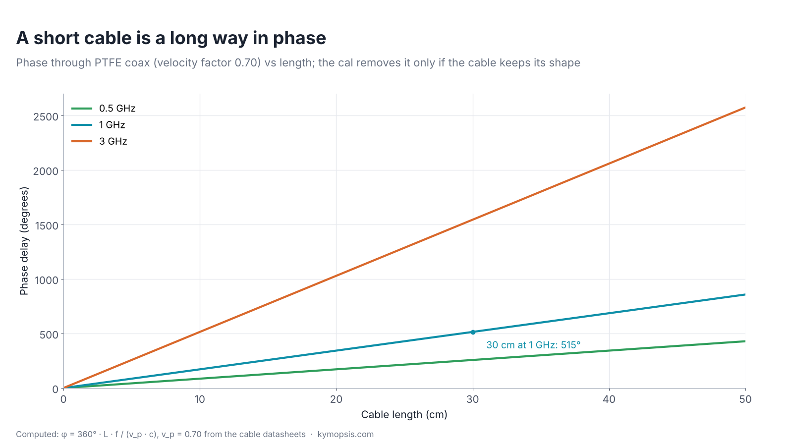
Cable loss rarely spoils a VNA measurement, because the calibration removes it. Phase is the issue. Coax with a solid PTFE dielectric carries the wave at about 70% of the speed of light (the datasheets give 0.70), so a 30 cm cable delays a 1 GHz signal by 515°, three times that at 3 GHz. The calibration takes those degrees out, but only for the cable as it lay during calibration. Bend it to reach the device and part of that delay changes, and the change looks like the device.
Two cable types make sense on a small VNA bench:
- Hand-formable .085 semi-flex (DC–18 GHz rated assembly, 6 mm minimum bend radius): you bend it once to the shape you need and it stays there, so calibration and measurement see the same cable. Loss is low: the datasheet gives at most about 0.4 dB for 20 cm and 0.8 dB for 50 cm at 3 GHz.
- Flexible RG316 (DC–3 GHz assembly, 15 mm minimum bend radius): for reaching an antenna on a mast or a device that moves. Re-run the calibration if you change how the cable lies, and keep it away from sharp bends at the connectors.
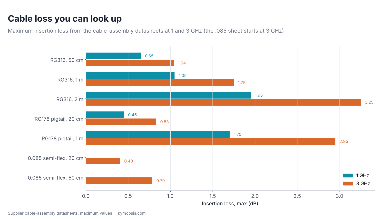
The thin RG178 pigtails in the chart (SMA to U.FL) are for connecting modules with tiny on-board connectors, not for test cables: a 1 m length loses about 60% more than 1 m of RG316 at 1 GHz (1.70 vs 1.05 dB, datasheet maxima).
Loss still matters in one case: measuring an antenna’s match at the far end of a long cable. The signal crosses the cable twice, so a cable with 2 dB of loss makes a poor antenna look 4 dB better matched than it is unless the calibration is done at the antenna end. Loss per metre for each cable type is in coax cable loss vs frequency.
Adapters: buy the ones your devices need
Most hobby and lab devices you will meet use SMA, BNC, N or UHF (SO-239/PL-259) connectors. A NanoVNA has SMA female ports, so the useful adapters are SMA to each of those, plus SMA female-female and male-male barrels to join cables (genders and the RP-SMA trap: SMA, RP-SMA, BNC and N adapter guide). Two habits keep them from causing errors:
- Leave one SMA male-to-female adapter permanently on each port as a connector saver; it keeps the port’s gender. It takes the wear of hundreds of connections, and replacing it is cheaper than replacing the analyzer’s port.
- Count adapters. Each one adds a small mismatch and loss; two or three in a row before the reference plane are fine, a stack after it is an error source.
The adapters we stock include SMA female-female and male-male barrels, right-angle adapters, BNC male to SMA female and N male to SMA male. The SMA adapters and the precision N to SMA adapter are rated DC–18 GHz; the standard BNC to SMA adapter is rated to 4 GHz, and a precision version to 18 GHz. UHF adapters are not in the range at the moment.
Protecting the ports: pads and a DC block
The ports of a low-cost VNA are built for its own small test signal. Two situations can push far more into them: measuring an amplifier, and connecting to a line that carries DC (an active antenna fed through the coax, an LNA with bias-tee power). For the amplifier, put an attenuator on its output so the analyzer’s second port sees roughly the level the amplifier was driven with: a 20 dB pad after a 20 dB amplifier. Enter the pad value as an offset, or include the pad in the thru calibration. For DC, put a DC block between the line and the port. The one we stock is rated from 30 MHz; below that, include it in the calibration and expect reduced accuracy. The full reasoning, with numbers, is in our guide to choosing an attenuator to protect an analyzer input.
A 50 ohm load is a reference you can trust
A spare 50 Ω termination is the quickest sanity check after calibration: connect it and the return loss should read at least the load’s rated value; a much lower reading means the calibration or a connector is bad. It also terminates the unused port of a divider or coupler during a measurement. The one we stock is rated DC–18 GHz with VSWR ≤1.25 (return loss at least 19 dB) and 0.5 W. That is good enough for a check and for terminating ports; the load in your calibration kit is the one the analyzer was calibrated with, so keep it for calibration. What VSWR and return loss mean is in 50 ohm, VSWR and return loss explained.
A short list
| Item | Why | When |
|---|---|---|
| Two .085 semi-flex cables, 15–30 cm | stable phase between cal and measurement | always |
| SMA male-to-female adapter | connector saver on each port | always |
| SMA female-female and male-male barrels | joining cables and gender changes | always |
| SMA to BNC and N adapters (UHF if you work on HF radios) | reach the devices you actually test | as your devices need |
| RG316 cable, 50 cm–1 m | reach antennas and moving parts | antenna work |
| 20 dB and 30 dB pads | amplifier outputs, unknown sources | amplifier work |
| DC block | lines with bias or supply voltage | active antennas, LNAs |
| Spare 50 Ω load | quick check, terminating spare ports | always |
The rest of the list (DC block, 50 Ω load, RG316 cables, BNC and N adapters) is in the RF catalog.
-
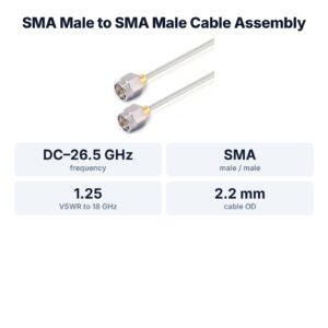
SMA Male to SMA Male Cable Assembly, .086″ Semi-Flexible Coax Cable Without FEP Jacket, DC–26.5 GHz
From $42.00Reset options100 mm150 mm200 mm250 mm300 mm400 mm500 mm800 mm1000 mmSelect options This product has multiple variants. The options may be chosen on the product page -

SMA Male to SMA Female Straight Adapter, DC–18 GHz
$8.00 Buy Now -

SMA RF Fixed Attenuator, DC–18 GHz, 50 Ohm, 1dB to 30dB, Stainless Steel Body, 2W
$35.00Reset options1 dB2 dB3 dB4 dB5 dB6 dB7 dB8 dB9 dB10 dB15 dB20 dB30 dBSelect options This product has multiple variants. The options may be chosen on the product page
FAQ
Do I need to recalibrate when I change cables?
Yes. The calibration belongs to the exact chain it was done with. A different cable, an added adapter or a cable bent into a new shape all need a new calibration for accurate phase and match.
Is a more expensive cable always better for a NanoVNA?
Not for loss, which calibration removes. What matters is that the cable keeps its phase when handled; a hand-formable .085 cable bent once and left alone does that well and costs little.
Can I measure an amplifier directly?
Put an attenuator on the amplifier’s output first, sized to its gain, and include it in the calibration or as an offset. Without it the second port may see far more than it is designed for.
What does a connector saver do?
It is an adapter left on the analyzer port permanently. All the connecting and disconnecting wears the adapter instead of the port, and a worn adapter is cheap to replace.
Sources and method
- Supplier cable-assembly datasheets: .085 semi-flex SMA–SMA (insertion loss by length, 3–18 GHz), RG316 SMA–SMA (DC–3 GHz), RG178 SMA–IPEX (DC–6 GHz). Velocity of propagation 70%.
- Supplier datasheets: SMA termination (DC–18 GHz, VSWR ≤1.25, 0.5 W), DC–18 GHz SMA attenuators, 30 MHz–27 GHz SMA DC block.
- Keysight application note 1287-3, Applying Error Correction to Network Analyzer Measurements (reference plane, calibration standards).
Phase figures are computed from the velocity factor in the datasheets; loss figures are the datasheet maxima, not our measurements.