


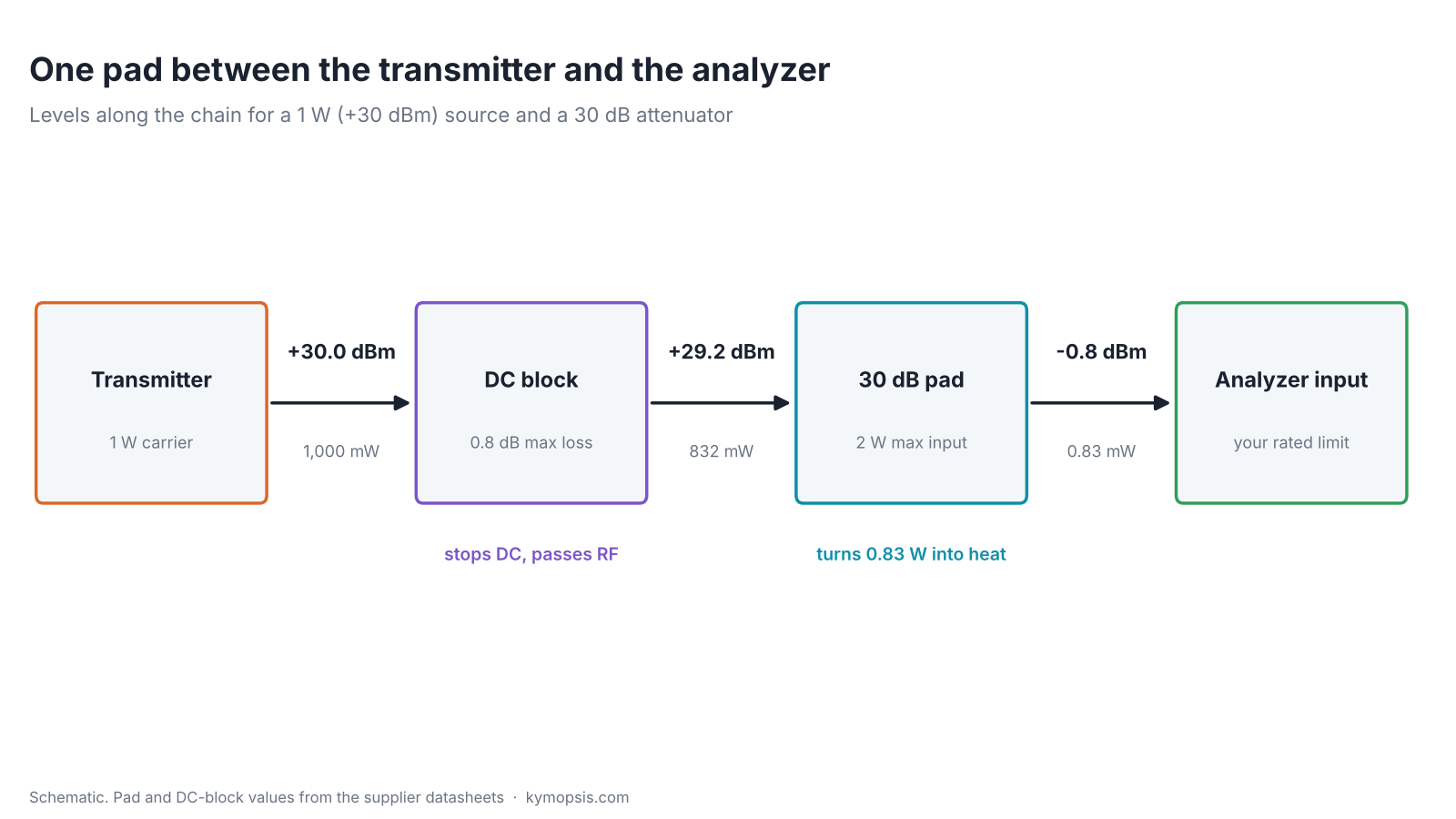
A handheld radio on its 1 W setting puts out +30 dBm. Hand-held spectrum analyzers, SDR dongles and pocket VNAs are built to look at signals thousands of times smaller, and most of them print a maximum input level next to the port or in the manual. Connect the radio straight to that port and the front end, not the display, is what takes the hit. A fixed SMA attenuator in front of the input lowers everything by a known number of decibels: 30 dB turns 1 W into 1 mW. Picking one comes down to three numbers: how many dB, how many watts the pad itself can take, and whether DC can reach the port.
How much attenuation: work in dBm
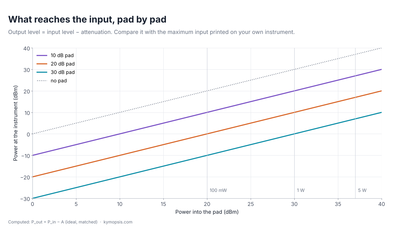
Power in dBm is decibels relative to 1 mW: 0 dBm is 1 mW, +10 dBm is 10 mW, +30 dBm is 1 W, +37 dBm is 5 W. In dBm, an attenuator is plain subtraction: the level at the instrument is the level at the source minus the pad value. So the pad you need is the source level minus the input limit of your instrument, plus a margin for the source being stronger than you think.
Pout (dBm) = Pin (dBm) − A (dB)
| Source | Level | After 10 dB | After 20 dB | After 30 dB |
|---|---|---|---|---|
| Wi-Fi or BLE module, 100 mW | +20 dBm | +10 dBm (10 mW) | 0 dBm (1 mW) | −10 dBm (0.1 mW) |
| Handheld radio, 1 W setting | +30 dBm | +20 dBm (100 mW) | +10 dBm (10 mW) | 0 dBm (1 mW) |
| Handheld radio, 5 W setting | +37 dBm | +27 dBm (500 mW) | +17 dBm (50 mW) | +7 dBm (5 mW) |
Two practical rules. If you do not know the source level, start with the biggest pad you have and remove pads until the signal sits comfortably on screen; the reverse order can be expensive. And measure transmitters with a pad even when the calculated level looks fine: a transmitter can briefly overshoot its set power when it keys up.
The pad has a power limit too
An attenuator does not make the power disappear; it turns it into heat. A 30 dB pad passes 0.1% of the input and absorbs the other 99.9%, so 1 W in means just under 1 W of heat in a small SMA body. The DC–18 GHz pads we sell are rated for 2 W maximum input. Their datasheet gives no derating curve; small pads in general lose rating as they get hot, so in a warm enclosure leave margin below 2 W.
Pheat = Pin · (1 − 10−A/10)
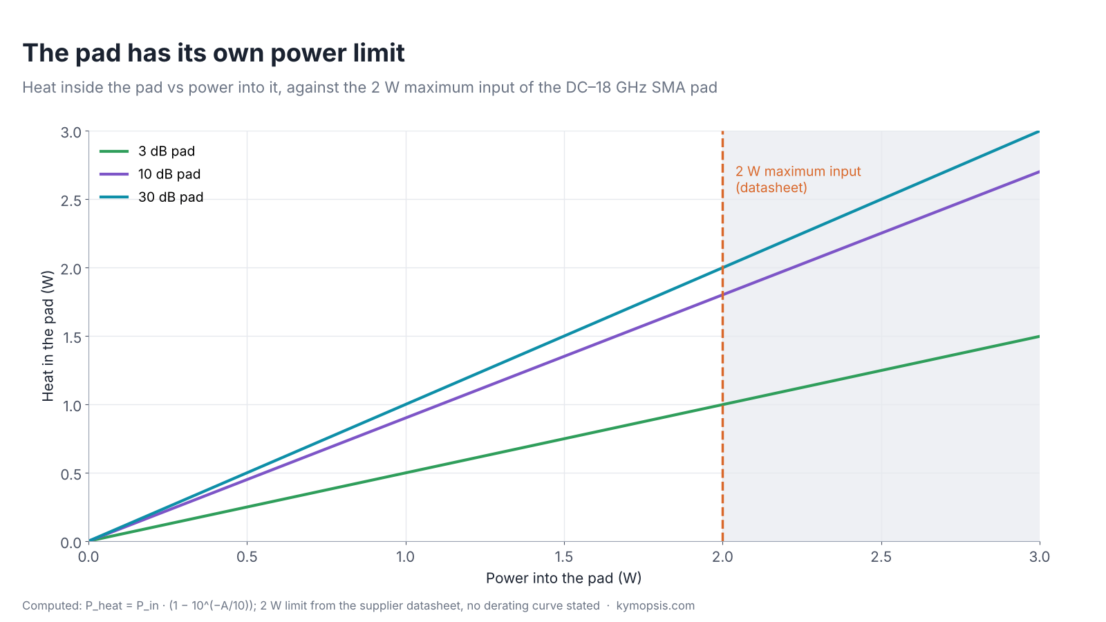
So a 5 W transmitter needs a high-power attenuator first (they come with fins or a heatsink), with the small SMA pad after it if you need more dB. Stacking two 2 W pads does not help: the first pad in the chain still takes almost all of the heat. The datasheet gives no peak or pulse rating, so treat 2 W as the limit and ask us before using these pads on high-power pulses.
Why the first pad takes the heat in a stack
With a 20 dB pad followed by a 10 dB pad, the first pad receives Pin and absorbs 99% of it. The second only receives 1% of Pin and absorbs 90% of that, 0.9% of Pin. Swapping the order changes the heat split to 90% in the 10 dB pad and 9.9% in the 20 dB pad. Either way the pad facing the source gets at least 90%.
DC goes straight through a resistive pad
A fixed attenuator is a resistor network all the way down to DC. Terminated in 50 Ω it divides a DC voltage by the same ratio as the RF voltage; if the instrument input is open at DC, more gets through. The pad also looks like about 50 Ω to whatever drives the line, so 12 V of bias puts 144/50 ≈ 2.9 W into it, above its 2 W rating. This matters when you probe a line that powers an LNA or an active antenna through the coax, or a circuit node that sits at a DC level. Many low-cost instruments state a DC limit at the input as well as an RF limit.
The fix is a DC block: a series capacitor in an SMA body. The one we stock passes 30 MHz–27 GHz with at most 0.8 dB loss and takes up to 2 W of RF. Put it first in the chain, at the source side, so the pad never sees the DC either. Its datasheet does not state a DC voltage rating, so check the bias voltage with us before blocking a 12 or 24 V line. It is specified only from 30 MHz: below that the capacitor’s reactance rises and the loss is not guaranteed, so for LF, MF and HF leave it out and make sure the line carries no DC.
What the pad costs you: sensitivity
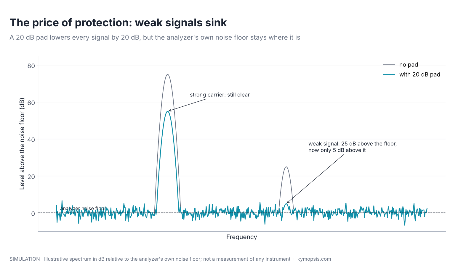
An analyzer’s displayed noise floor comes from its own front end. A pad lowers your signal but not that noise, so every dB of protection is a dB of lost sensitivity. Strong carriers do not care; a weak spur or a distant station may drop into the noise. The usual practice is two setups: a pad for transmitter tests and unknown sources, and no pad, or a smaller one, once you know the level is safe.
A side benefit: a better match
A pad also hides a poor match: whatever the instrument reflects crosses the pad twice, so an ideal 10 dB pad adds 20 dB of return loss. That is why a 3 or 6 dB pad is often left on a mixer or amplifier port during measurements. The pad’s own reflection sets a ceiling: the pads we stock are specified at VSWR 1.25, about 19.1 dB. The worst-case numbers are worked out in RF attenuators explained.
Which pads to keep on the bench
| Job | Pad | Why |
|---|---|---|
| Look at a transmitter up to about 1 W | 30 dB (DC block first if DC can be present) | +30 dBm becomes about 0 dBm; under 1 W of heat |
| General protection for unknown sources | 20 dB | keeps 100 mW-class modules near 0 dBm |
| Tame a reflective port, VNA or mixer work | 3–6 dB | adds 6–12 dB of return loss for a small level drop |
| Fine level steps | 3, 6, 10, 20 and 30 dB | combine for 3 to 69 dB; tolerances add |
Accuracy is part of the choice: the datasheet gives ±0.4 dB for the 1–5 dB values, ±0.5 dB for 6–10, ±0.6 dB for 15 and 20 and ±0.8 dB for 30. For a known level you still need to measure the pad at your frequency, or add the tolerance to your margin.
Pads with other connectors and power ratings are in the attenuators and terminations section of the RF catalog.
Formula sheet
Every formula and key number from this page on one A4 sheet, to print or keep next to the bench: download the formula sheet (PDF, 1 page). Free to print and share.
-

SMA RF Fixed Attenuator, DC–18 GHz, 50 Ohm, 1dB to 30dB, Stainless Steel Body, 2W
$35.00Reset options1 dB2 dB3 dB4 dB5 dB6 dB7 dB8 dB9 dB10 dB15 dB20 dB30 dBSelect options This product has multiple variants. The options may be chosen on the product page -
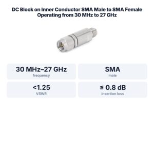
DC Block on Inner Conductor SMA Male to SMA Female Operating from 30 MHz to 27 GHz
$73.00 Buy Now
FAQ
Can I use one 30 dB pad for both RF and DC protection?
No. A resistive pad passes DC in proportion. Use a DC block in front of the pad when a DC voltage can be on the line.
Does an SMA attenuator work below 1 MHz?
Yes. The pads are rated from DC to 18 GHz. A DC block is the part that loses performance at low frequency; the one we stock is rated from 30 MHz.
How do I know my instrument’s input limit?
It is usually printed next to the input port and stated in the manual, often as a maximum RF level in dBm and a maximum DC voltage. Use the lower of the printed and documented values.
Why is my reading 30 dB lower than expected after adding a pad?
Many analyzers have a reference-level offset or external attenuation setting. Enter the pad value there and the display shows the level at the pad’s input.
Sources and method
- Supplier datasheet, DC–18 GHz SMA fixed attenuator: DC–18 GHz, VSWR 1.25, 2 W maximum input, accuracy ±0.4 dB (1–5 dB) to ±0.8 dB (30 dB); no derating or pulse rating stated.
- Supplier datasheet, SMA inner DC block: 30 MHz–27 GHz, insertion loss ≤0.8 dB, VSWR <1.25, 2 W; no DC voltage rating stated.
- D. M. Pozar, Microwave Engineering, 4th ed., Wiley, 2012: attenuators, return loss and mismatch.
Levels, heat and return-loss figures are computed from the formulas shown (ideal matched pads); the spectrum figure is an illustration in dB relative to the noise floor, not a measurement of any instrument.