


Almost every connector on an RF bench says 50 Ω, and almost every datasheet gives a VSWR or a return loss. They describe the same thing: how much of a signal bounces back when it reaches the end of a cable. A 50 Ω load at the end of a 50 Ω line absorbs everything; anything else reflects part of the wave, and VSWR, return loss and the reflection coefficient are three ways of saying how much. This page explains where 50 Ω comes from, how to convert between the three numbers, and what a termination is for.
Why 50 Ω
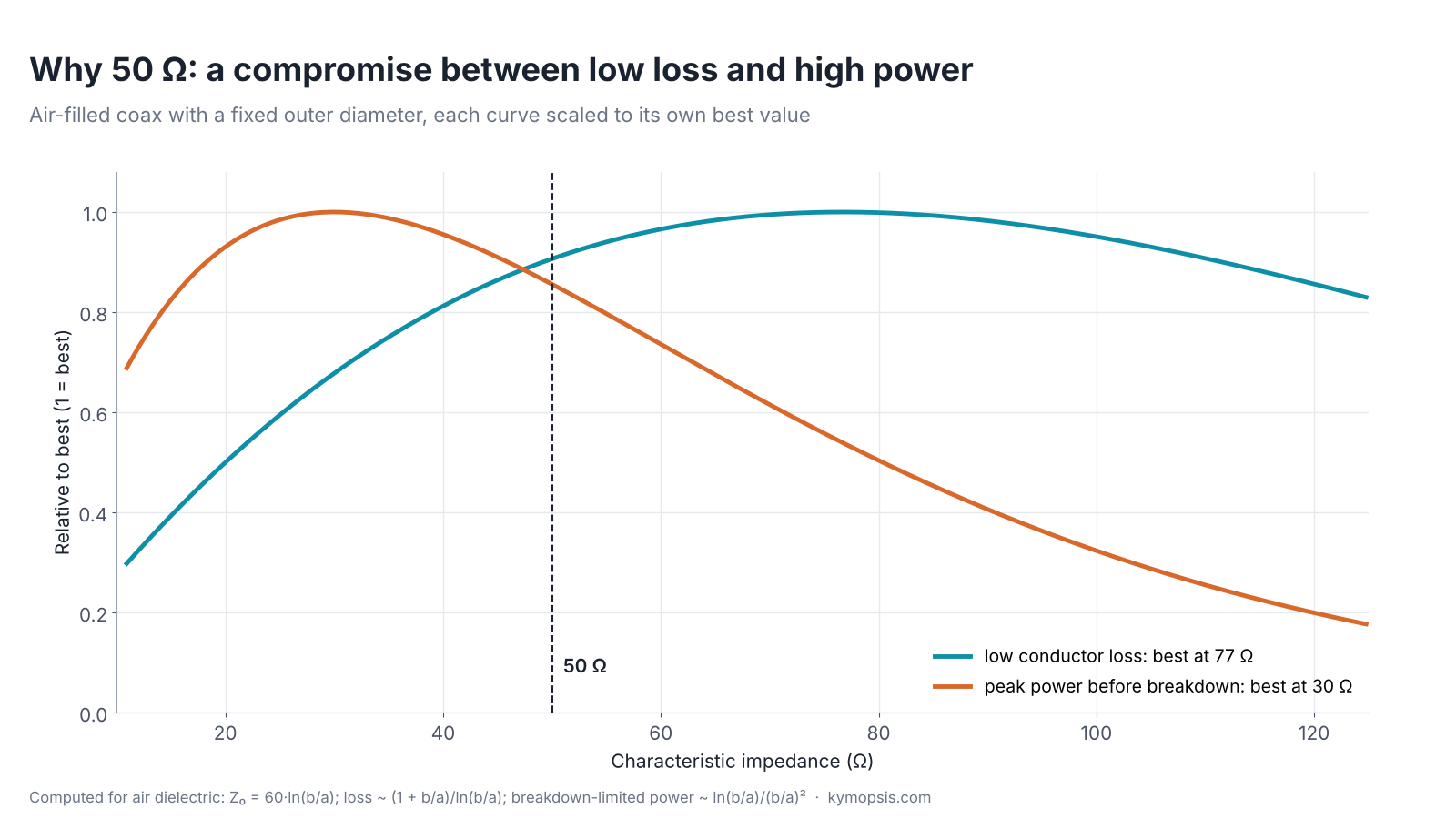
The impedance of a coax is set by the ratio of its outer and inner conductor diameters and by the insulation between them. For an air-filled line with a fixed outer size, the ratio that gives the lowest conductor loss corresponds to about 77 Ω, and the ratio that carries the most power before the air breaks down corresponds to about 30 Ω. 50 Ω sits between the two and gives up little of either. It became the standard for test equipment, radios and RF modules; 75 Ω, close to the low-loss optimum for an air line, stayed the standard for video and TV where power is low.
What matters in practice is that every part in a chain uses the same impedance. A source, a cable and a load all at 50 Ω pass the signal without reflections; mixing in a 75 Ω part creates a step, as our adapter guide shows for 75 Ω BNC.
Reflection, return loss and VSWR
When a wave on a 50 Ω line meets a load of impedance Z, the ratio of the reflected to the incoming voltage is the reflection coefficient:
Γ = (Z − Z0) / (Z + Z0)
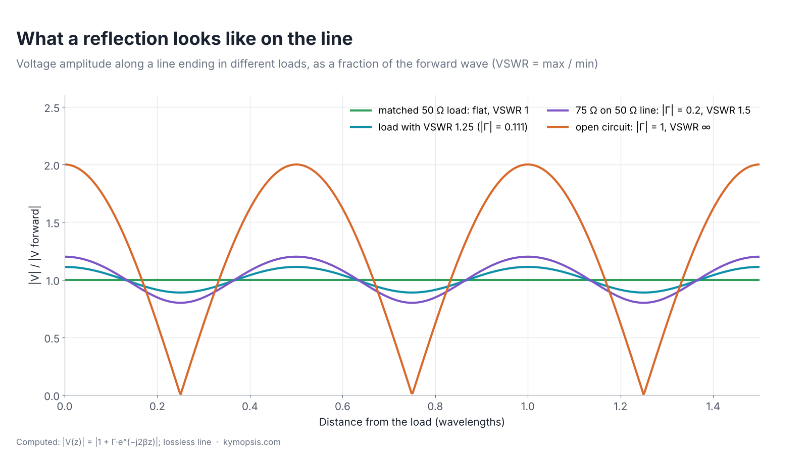
A 50 Ω load gives Γ = 0. An open circuit gives +1 and a short −1: everything comes back. Return loss is how far below the incoming wave the reflection is, in dB, so bigger is better. VSWR comes from the pattern the two waves make on the line: where they add the voltage peaks, where they oppose it dips, and VSWR is peak divided by dip.
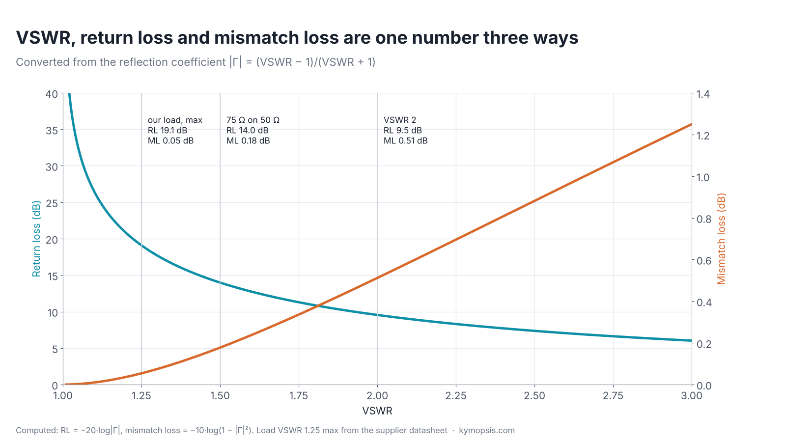
RL = −20·log10|Γ| VSWR = (1 + |Γ|) / (1 − |Γ|) mismatch loss = −10·log10(1 − |Γ|²)
| VSWR | |Γ| | Return loss | Power reflected | Mismatch loss |
|---|---|---|---|---|
| 1.1 | 0.048 | 26.4 dB | 0.2% | 0.01 dB |
| 1.25 | 0.111 | 19.1 dB | 1.2% | 0.05 dB |
| 1.5 | 0.200 | 14.0 dB | 4.0% | 0.18 dB |
| 2.0 | 0.333 | 9.5 dB | 11.1% | 0.51 dB |
| 3.0 | 0.500 | 6.0 dB | 25.0% | 1.25 dB |
The table explains a common surprise. An antenna at VSWR 2 reflects about 11% of the power, so only about 0.5 dB is lost to the mismatch. For a receive antenna that is often unnoticeable. The reasons to care about match are elsewhere: a transmitter or amplifier may not like the reflected power, a mismatch at both ends makes levels depend on cable length, and in measurements every reflection is an error term.
Why the ripple repeats every half wavelength
The reflected wave travels back, so at a distance z from the load it has covered 2z more than the incoming wave. The two waves come back into the same phase every time 2z grows by a whole wavelength, which is every half wavelength of line. That is why moving a probe along a slotted line, or changing a cable length, moves you between peaks and dips.
What a 50 Ω termination is for
A termination, or load, is a 50 Ω resistor built into a connector so that it looks like an endless 50 Ω line: whatever arrives is absorbed as heat. Typical uses on a bench:
- Closing unused ports of a splitter, coupler or multi-port board, so their reflections do not disturb the ports you use.
- The “load” standard in a VNA calibration, together with open and short; see our NanoVNA accessories guide.
- A quick check: after calibration, the load should read at or better than its specified return loss; a worse reading points to a bad calibration, connector or cable. It cannot show anything smaller than its own reflection, about 19 dB return loss for the one we stock.
- A dummy load for a low-power transmitter or a signal generator, within its power rating.
The datasheet numbers that matter are the frequency range, the VSWR and the power rating. The SMA male load we stock is specified at VSWR ≤1.25 from DC to 18 GHz and 0.5 W. That VSWR means a return loss of at least 19.1 dB: good enough for unused ports and for calibrating a hobby VNA, where the result can be no better than the load used. The 0.5 W rating is for bench signals, not for a transmitter on full power; for that, use a high-power dummy load, or put an attenuator rated for the full power in front so the load only sees what is left. Our attenuator explainer shows how a pad also improves the match a source sees.
Measuring match
A VNA measures Γ directly and shows it as return loss, VSWR or a point on a Smith chart. Remember that the result includes everything after the calibration plane, and that a measurement through a cable shows the cable’s loss twice: a 1 dB cable makes a load look 2 dB better in return loss than it is. Calibrate at the end of the cable, or subtract the cable.
Loads with other connectors and power ratings are in the attenuators and terminations section of the RF catalog.
Formula sheet
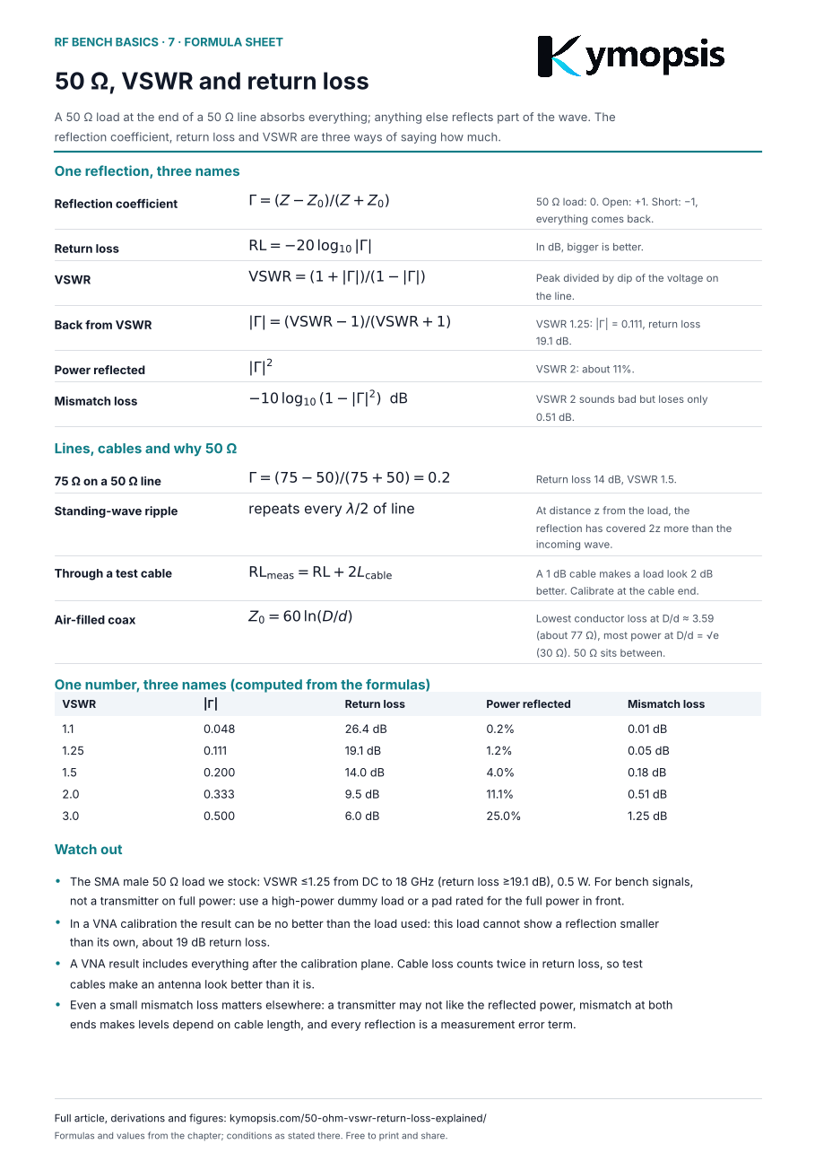
Every formula and key number from this page on one A4 sheet, to print or keep next to the bench: download the formula sheet (PDF, 1 page). Free to print and share.
-
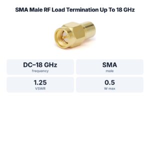
SMA Male RF Load Termination Up To 18 GHz, 0.5 Watts, Gold Plated Brass
$15.00 Buy Now -

SMA RF Fixed Attenuator, DC–18 GHz, 50 Ohm, 1dB to 30dB, Stainless Steel Body, 2W
$35.00Reset options1 dB2 dB3 dB4 dB5 dB6 dB7 dB8 dB9 dB10 dB15 dB20 dB30 dBSelect options This product has multiple variants. The options may be chosen on the product page -

SMA Male to SMA Female Straight Adapter, DC–18 GHz
$8.00 Buy Now
FAQ
What is a good VSWR?
It depends on the job. Below 1.5 (return loss above 14 dB) is a common target for antennas; test-port loads and adapters are usually specified tighter. The SMA load we stock is specified at 1.25 or better to 18 GHz.
Is return loss the same as insertion loss?
No. Return loss is about what bounces back from a port; insertion loss is about what is lost going through a part.
Why is return loss positive if it is a loss?
It is the ratio of incoming to reflected power in dB. A larger number means a smaller reflection.
Can I use a 50 Ω load as a dummy load for my radio?
Only within its power rating. The SMA load we stock is rated 0.5 W, which is for bench signals, not a transmitter on full power.
Why do test cables make my antenna look better?
The reflection crosses the cable twice, so cable loss adds twice to the measured return loss. Calibrate at the cable end.
Sources and method
- Supplier datasheet for the SMA male 50 Ω load we stock: DC–18 GHz, VSWR 1.25 to 18 GHz, 0.5 W.
- D. M. Pozar, Microwave Engineering, 4th ed., Wiley, 2012: reflection coefficient, standing waves, return loss, mismatch loss, coaxial line impedance.
All curves and table values are computed from the formulas shown; the only product figures are from the datasheet.