



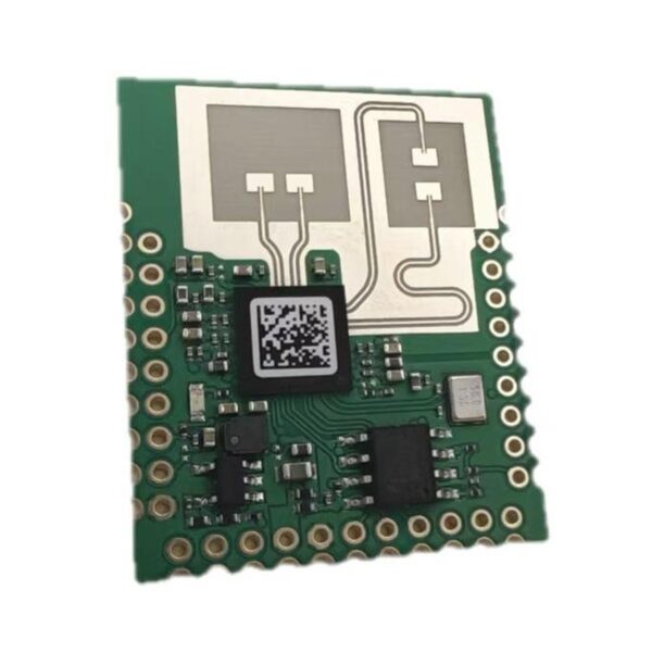







This is a 60 GHz radar module with two transmit and two receive PCB patch antennas, for presence and people tracking, people counting, gesture control, fall-event, breathing / heart-rate and 3D point-cloud projects. Kymopsis sells it as a development kit for product developers and integrators.
Applications
Pick one when you order and the board ships pre-flashed with it. The development kit includes every build below, so you can switch between them with the programmer. Figures come from the chip maker’s application notes for this 2T2R module, not from a Kymopsis lab test, and depend on mounting and the room.
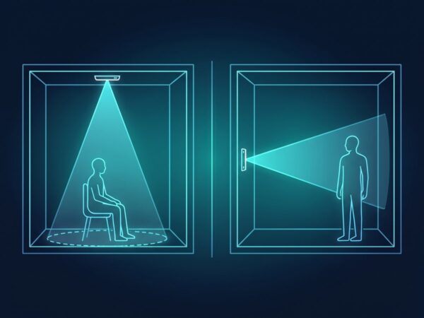
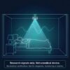
- Presence and tracking: ceiling or wall mount. Covers the full circle below a ceiling unit and about ±55° in front of a wall unit; follows up to 4 people out to about 6.5 m; switches to occupied within about 0.5 s and back to empty about 5 s after the room clears, with an adjustable hold time for people sitting still. Three sensitivity levels, detection and ignore zones (to mask fans or plants), adjustable detection height, and a low-power mode while the room is empty.
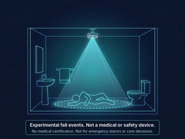
- Presence and fall events (experimental): ceiling mount at a height you set between 1 and 5 m, with a configurable alert zone; reports a fall flag and the target’s height above the floor.
- People counting: ceiling or wall mount; tracks people as they move and keeps a count for up to 5 rectangular zones you draw.
- Gesture recognition: six hand swipes (up, down, left, right, toward and away), board facing the user.
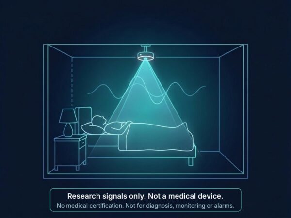
- Breathing and heart rate (research): contactless, one person, board above the chest; reports breathing rate, heart rate and distance.
- 3D point cloud (development kit): x, y, z position, speed and signal strength for each detected point, for your own tracking or entry-detection code.
- Basic ranging (development kit): range, speed and signal strength of the strongest target, a good first test of the module.
The application builds sweep 2 to 4 GHz inside the 57–62 GHz range; a 4 GHz sweep separates targets about 3.75 cm apart in range.
Mounting and coverage
- Ceiling builds: antenna facing down, centred over the area; presence and tracking covers the full circle below the board.
- Wall builds: antenna facing into the room; covers about ±55° in front of the board, up to 4 people to about 6.5 m (21 ft).
- Fall events (experimental): ceiling mount at a height you set between 1 and 5 m (3.3–16 ft).
- Gesture: board facing the user.
- Breathing and heart rate (research): one person, board above the chest.
Figures come from the chip maker’s application notes, not a Kymopsis lab test, and depend on mounting and the room.
Avoid these in the detection area
Most false or missed detections come from the room, not the module. Check these before you change any setting:
- Things that move on their own: fans, curtains in a draught, swaying plants, pets. Point the board away from them, or mask them with the presence build’s ignore zones.
- Metal near the antenna: keep the antenna area clear of metal. A metal case, metallised film or coated glass in front of the board blocks 60 GHz; use a thin plastic cover instead.
- Large mirrors and metal surfaces in the room can create reflected ghost targets.
- A mount that vibrates, such as a door, an appliance lid or a loose bracket, looks like motion to the radar.
- Two radars facing each other at close range can disturb each other; angle them apart.
- A weak 3.3 V supply: the module draws up to 600 mA. Power it from the included LDO module or adapter, not from the small 3.3 V pin of a typical USB-serial adapter.
Not a medical device
Fall, breathing and heart-rate outputs are experimental research signals. The board has no medical certification and must not be used to diagnose, monitor or treat any condition, or as a safety or emergency alarm.
AiP or PCB-antenna board?
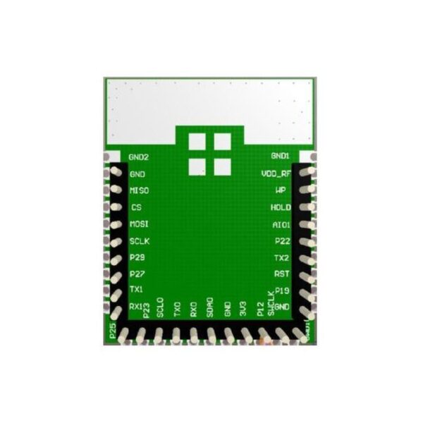
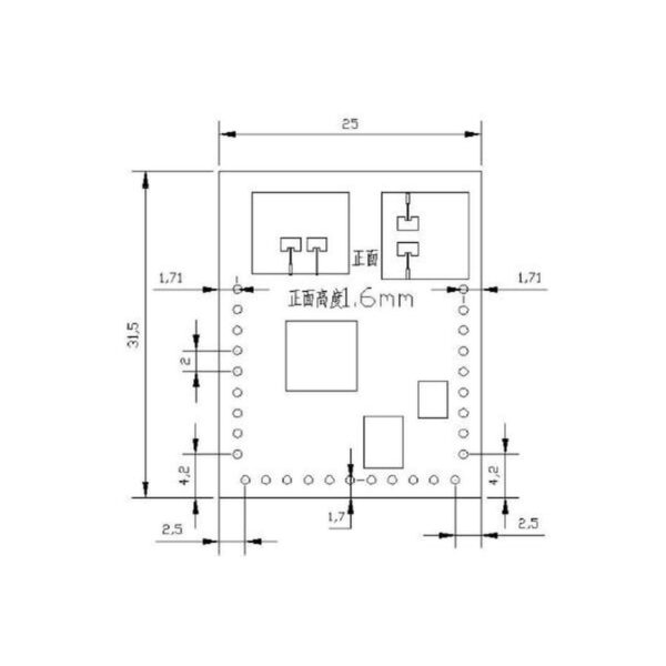
Both run gesture and presence applications and the same open-source demos; pick by size and how you connect it. The AiP board has its antennas inside the chip package, so it fits a 42 × 8 mm strip for tight spaces; the PCB-antenna board carries 2T2R patch antennas on a 25 × 31.5 mm board with castellated pads and 2.0 mm pitch pin headers that plug straight into the interface board. See the AiP board.
Specifications
From the supplier datasheet, not a Kymopsis lab report.
- Band: 60 GHz (the datasheet table states 58–62 GHz)
- Antenna: 2T2R PCB microstrip; stated gain 4 dBi; stated −3 dB beam ±60° horizontal and elevation
- Stated transmit power: 12 dBm typical
- Interfaces on the pads: UART, I2C, SPI, SWD
- Supply: 3.1–3.5 V, typical 3.3 V; maximum current 600 mA
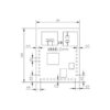
- Size: 25 × 31.5 mm
- Connection: castellated pads with 2.0 mm pitch pin headers on three edges (pitch from the supplier drawing), for the interface board or soldering to your own board. Not 2.54 mm: standard Dupont jumper wires and breadboards do not fit directly, so the DIY board ships with 2.0 mm to 2.54 mm jumper wires.
- Operating temperature: −20 °C to 85 °C; storage −40 °C to 85 °C
The module datasheet states no detection range; see the application figures above.
What you need
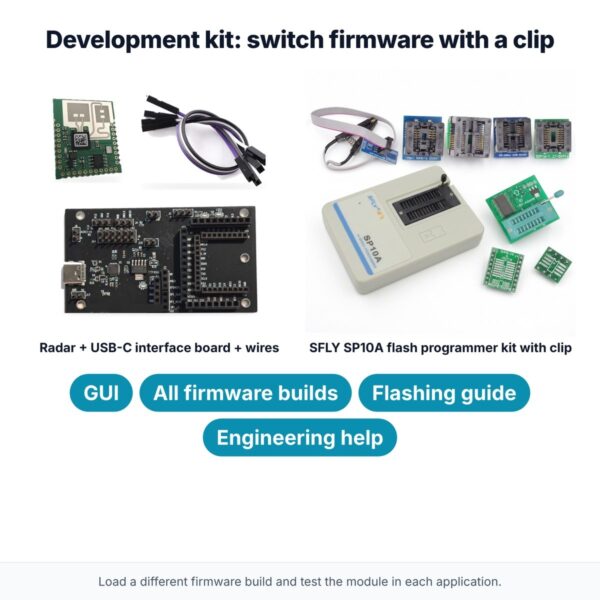
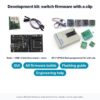
Development kit: everything is included. The board plugs into the USB-C interface board, which has an on-board 3.3 V LDO supply, USB-C serial to the GUI and labelled headers for the included jumper wires. The kit also includes the SFLY SP10A programmer kit, so you can switch between firmware builds and test the module in each application.
DIY board: the headers are 2.0 mm pitch, so the board ships with 2.0 mm to 2.54 mm female–female jumper wires that connect it to a standard 2.54 mm USB-to-TTL adapter or microcontroller header. You also need a 3.3 V UART (a USB-to-TTL adapter or a microcontroller). Power comes from the free AMS1117 3.3 V LDO module (rated 800 mA) included with the DIY board, fed from any 5 V source. For your own product, solder the castellated pads or fit a 2.0 mm socket on your carrier PCB.
Changing the firmware
The board ships with the application you pick, and the GUI tunes it over UART. With the development kit you can load any of the firmware builds and compare applications on the same module. The development kit includes the SFLY SP10A programmer kit for this: its clip goes onto the flash chip and writes the new firmware file directly, no debugger needed. The flashing guide walks through it.
Open-source demos
These projects run on either 60 GHz board: the AiP sensor or the PCB-antenna DIY board. Order the board with the application named in each project’s README.
- Radar desk buddy: an ESP32-S3 desk companion whose eyes and figure follow you (Presence, wall mount).
- Radar auto-lock: locks your PC when you walk away and wakes it when you return, as a USB or Bluetooth keyboard (Presence, wall mount).
Guides and background
- Radar Principles 11: Micro-Doppler and Vital Signs
- Radar Principles 16: Detection and Tracking with CFAR and Kalman Filters
- Radome Design for 60 & 77 GHz Radar: Thickness, Angle, Water
Datasheet
Download the Kymopsis datasheet (PDF): specifications, pin functions, mechanical data, and integration notes.
Regulatory status
Not FCC certified, and no CE or other certification is claimed. It is sold as a development kit for engineers and integrators, not as an authorized end product. If your own product needs equipment authorization, the B2B program can scope the integration and the lab and TCB process.













Reviews
There are no reviews yet.