



An antenna does not create power; it decides where the power goes. How much it concentrates in one direction (the gain), how wide the main beam is and how much leaks into sidelobes are set mainly by the size of the radiating aperture measured in wavelengths. Together they decide how far a radar can see and what else it sees on the way. This chapter gives those rules first and then applies them to a real case.
We sell two 80 GHz radar level sensor boards that use the same radar chip, the same 12 dBm transmit power and the same UART protocol. The module maker rates one for 20 m (30 m with its lens radome) and the other for 60 m. The chip is not the reason. The main hardware difference is the antenna: the 20 m board transmits and receives through two separate patch groups, while the 60 m board sends both through one waveguide horn and then a lens. A shared horn gives the lens a single feed point on its axis and puts far more of its power onto the lens. Two separate patches can do neither, and the gap grows as soon as you try to narrow the beam.
Below is how that works, with the maker’s numbers, a few plain formulas you can check, and photos of the actual boards. Where a number is our estimate or a model rather than a datasheet value, we say so.
This post is chapter 4 of Radar Principles. The first section gives the general antenna rules, gain, beamwidth and sidelobes from aperture size; the rest applies them to two real boards. It builds on interference (chapter 3), which explains why a large in-phase aperture makes a narrow beam. Later chapters use the results: chapter 7 puts antenna gain into the radar equation, chapter 13 covers the plastic in front of the antenna and chapter 17 steers the beam with an array.
Aperture, gain, beam and sidelobes
Shout through cupped hands and your voice carries further straight ahead; shout through a megaphone, a wider opening, and it carries further still, in a narrower cone. Someone standing beside the megaphone still hears a little. An antenna works the same way with radio waves: the wider its opening, measured in wavelengths, the narrower the beam and the more power goes straight ahead, and the little that still leaks sideways is the sidelobe.
A radar antenna turns the chip’s RF output into a wave in free space, and back. For radar, five properties matter: gain (how much more power goes into the main direction than an isotropic source would send), beamwidth, sidelobes, polarisation and the phase centre. The first three are set mostly by the size of the radiating aperture measured in wavelengths:
Start with what gain means, because the word misleads. An antenna does not amplify anything: the power it radiates is the power the chip delivers, minus small losses. Gain describes where that power goes. An imaginary isotropic antenna spreads it evenly over a whole sphere; a real antenna squeezes it into a narrower cone, so inside the cone the power per square metre is higher. Gain in dBi is that increase over the isotropic case. If all the power went into a 12° cone and none anywhere else, the density inside would be about 365 times higher, 26 dBi.

A horn or a lens gets its gain by making the radiating area large compared with the wavelength. A wave leaving a wide, flat, in-phase aperture can only travel straight ahead without its parts interfering destructively; towards the sides, waves from different parts of the aperture arrive out of step and cancel, the same arrow-adding picture as the array chapter. A horn widens a small waveguide into a big mouth, a lens straightens a curved wavefront into a flat one, and both end up with a large in-phase aperture. The formulas below put numbers on it.
G = 4π·A·η / λ² θ₃dB ≈ 0.886·λ / D (radians)
Here A is the aperture area, η its efficiency (0.5–0.8 for a good antenna), D its length in the plane of interest and θ₃dB the full −3 dB beamwidth for uniform illumination. Doubling the side of a square aperture adds 6 dB of gain and halves the beam. A 20 mm square gives about 21 dBi and a 12.6° beam at 60.5 GHz, and 23 dBi and 9.7° at 78.5 GHz; the same physical size holds more wavelengths at the higher frequency (chapter 20 compares the bands).

Gain and beamwidth are two views of the same thing. A rough rule, directivity ≈ 41,000 / (θE·θH) with the two beamwidths in degrees, gives about 4.5 dBi if ±60° is read as the −3 dB beam in both planes, close to the 4 dBi and ±60° stated for our AiP and PCB-antenna 60 GHz modules: their single elements are built for a wide field of view, which is what a presence or gesture sensor needs, not for reach.
A uniformly fed aperture has its first sidelobe about 13.3 dB below the main beam. Sidelobes let in echoes from directions the radar is not looking at, such as a tank wall or the road surface. Feeding the edges of the aperture more weakly than the centre (a taper) lowers the sidelobes at the cost of a wider beam and a little gain; chapter 17 shows the trade with numbers.
| Antenna type | How it gets its beam | In the kits we sell | Good for | Limits |
|---|---|---|---|---|
| PCB patch / patch array | Copper patches on an RF laminate; more patches, more aperture | 60 GHz PCB-antenna module (4 dBi, ±60°); 20 m level board (9 dBi, 100° × 80°) | Low cost, flat, MIMO layouts | Substrate loss at 77 GHz; size grows with gain |
| Antenna in package (AiP) | Elements on the chip package, typically about λ/2 apart | 60 GHz AiP module (4 dBi, ±60°) | Tiny modules, no RF board design | Little aperture: wide beams only |
| Horn, horn + lens | Waveguide flares into an aperture; a lens flattens the wavefront | 60 m level board (horn + PTFE lens) | High gain, narrow beam, one phase centre | Length, weight, cost |
Which one fits depends on the job. Measuring angle (chapter 12) needs several wide-beam elements about λ/2 apart, which favours patches and AiP. Reaching far into a narrow tank needs gain and a narrow beam from one phase centre, which favours a horn and lens. The rest of this post is a worked example of the second case: two level-radar boards with the same chip and very different range.
The two boards side by side
| 20 m board (PCB antenna) | 60 m board (horn + lens) | |
|---|---|---|
| Radar chip | 76–81 GHz FMCW single-chip SoC | Same chip |
| Transmit power | 12 dBm | 12 dBm |
| Antenna | PCB patch, 9 dBi, beam 100° × 80° (−3 dB, bare board) | Waveguide horn with PTFE lens; gain and beam not stated |
| Stated range | 15 m typical, 20 m standard, up to 30 m with the lens radome | Up to 60 m |
| Accuracy (measured) | ±2 mm | ±4 mm at any distance |
| Blind zone | 6 cm | 6 cm |
| Board | 2.54 mm pin headers | 35.3 × 55.3 mm, 2.0 mm dual-row headers |
All values are the module maker’s datasheet figures, not a Kymopsis lab report. The maker does not publish the chirp settings of either firmware, so we leave those out of the comparison.

Look at the 20 m board first. There are eight small copper patches, wired as two groups of four. One group transmits, the other receives. On the 60 m board there is no patch antenna at all. The chip feeds one round pad, and the aluminium horn bolts on top of it, so the transmitted signal and the echo travel through the same waveguide.
Reason 1: a lens wants one feed point, on its axis
A magnifying glass focuses sunlight into one bright dot, but only at one spot behind it. Two people cannot both stand on that spot: whoever stands a little to the side gets a dot that lands beside the target. Put a lens in front of the 20 m board and its transmit and receive patches are those two people.
Every antenna has a phase centre: the point the radiated wave seems to come from. A lens focuses well only for a source sitting at its focal point. Move the source sideways by a distance d, and the lens still makes a narrow beam, but tilted by roughly d/F radians, where F is the focal length. That is plain geometric optics, the same reason an off-centre LED in a torch throws its spot to one side.
On the 20 m board, the transmit group and the receive group cannot both sit at the focus. They are a few millimetres apart, so behind a lens the transmit beam leans one way and the receive beam leans the other. On the axis, where the liquid surface is, each one is already down its own slope. The radar needs both: what comes back is the transmit pattern multiplied by the receive pattern.
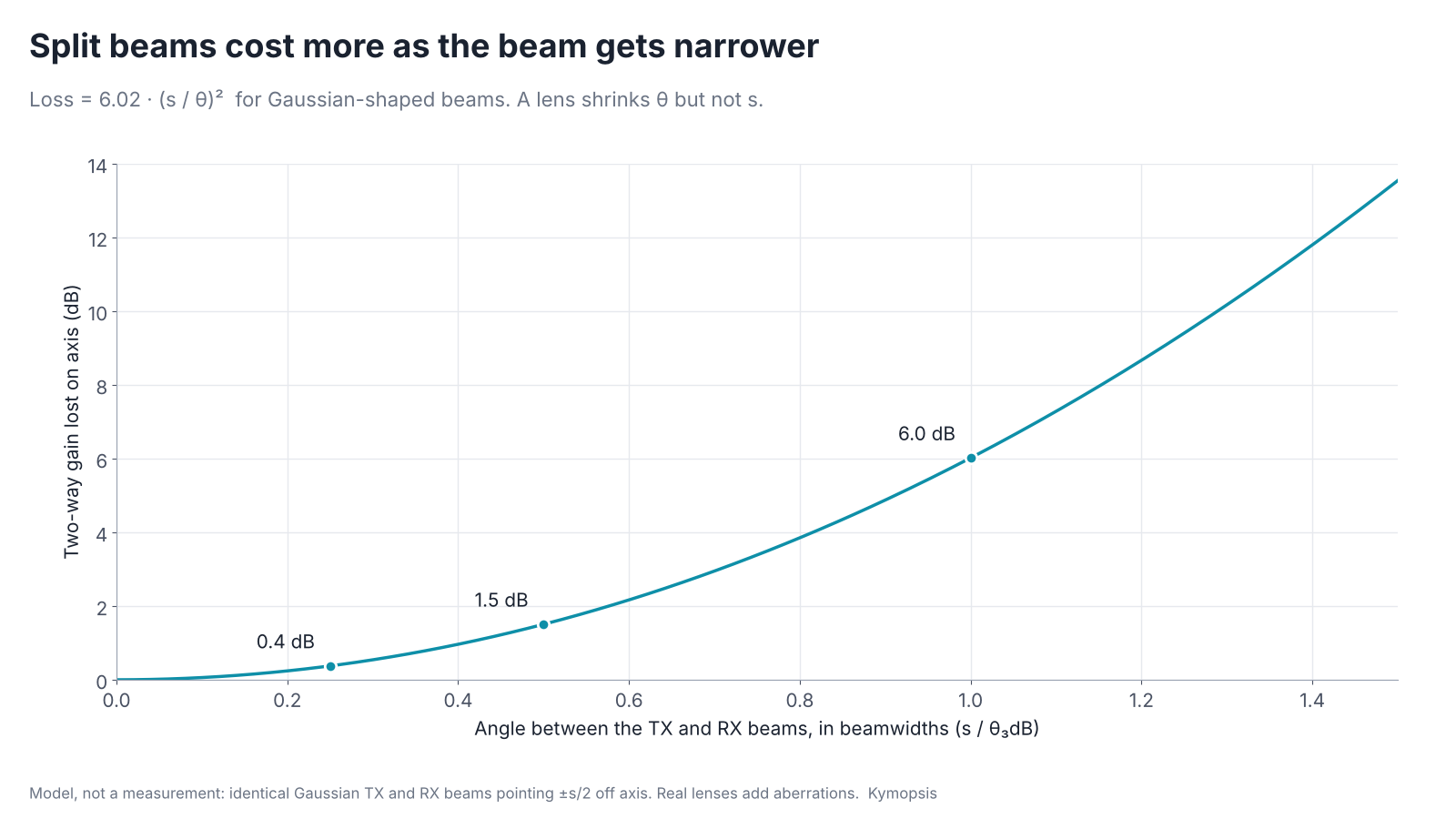
For two Gaussian-shaped beams of width θ pointing ±s/2 off axis, the on-axis two-way loss works out to 6.02 · (s/θ)² dB. Split them by half a beamwidth and you lose 1.5 dB. Split them by a full beamwidth and you lose 6 dB, which is a quarter of the power. The angle s is fixed by the patch spacing and the focal length, while θ shrinks as the lens gets wider. For a given focal length, the harder you try to narrow the beam, the more the split costs you; put another way, the loss is set by the patch spacing in wavelengths and the lens’s F/D. Without a lens both groups simply point straight ahead, and the offset only tilts the beams once a lens is added.
The horn does not have this problem. Transmit and receive leave from the same aperture, so there is one phase centre, it can be placed on the lens axis, and both beams point the same way by construction.
Reason 2: the horn puts its power on the lens, the patch does not
Hold a funnel under a garden sprinkler and most of the water misses it; hold the same funnel under a tap and nearly all of it goes in. The bare patch board is the sprinkler and the horn is the tap: a lens can only focus the power that actually lands on it.
A lens can only focus energy that actually hits it. The bare 20 m board radiates into a 100° × 80° cone (−3 dB). A lens sitting in front of it covers only part of that cone; the rest goes past the edge, hits the housing or leaves sideways. Antenna engineers call that spillover.

With a simple rotationally symmetric feed model, a lens whose edge is 20° off axis catches about 15 % of a 100° feed’s power and about 73 % of a 30° feed’s. The exact numbers depend on the real patterns and the real lens, which the maker does not publish, so treat them as an illustration of the trend. The point holds either way: a wide feed and a compact lens waste most of the power, and a horn exists precisely to shape the feed pattern so that the lens is evenly lit and less spills past it.
The horn on the 60 m board is a small aluminium part: a Ø2.7 mm round waveguide bore opening to a Ø7.8 mm mouth, 36.5 mm long with its flange, and an M14 × 1.5 thread that carries the PTFE lens.

What a few dB is worth on a liquid surface
Shine a torch at a mirror across a dark room and the reflection looks like a second torch twice as far away, not like a faint lit spot. A calm liquid surface is that mirror for a level radar, so its echo fades far more slowly with distance than the echo from a person, and every dB of antenna gain buys much more range.
It is tempting to think a few dB here and there cannot turn 20 m into 60 m. On a calm liquid surface it can, because a calm surface that is much larger than the first Fresnel zone (radius about √(λR/2), roughly 0.2 m at 20 m) reflects like a mirror. The echo then behaves like a signal from an image of the radar at twice the distance, so the received power falls as 1/R², not as 1/R⁴ as it does for a small target. Antenna gain counts twice, once on the way out and once on the way back.
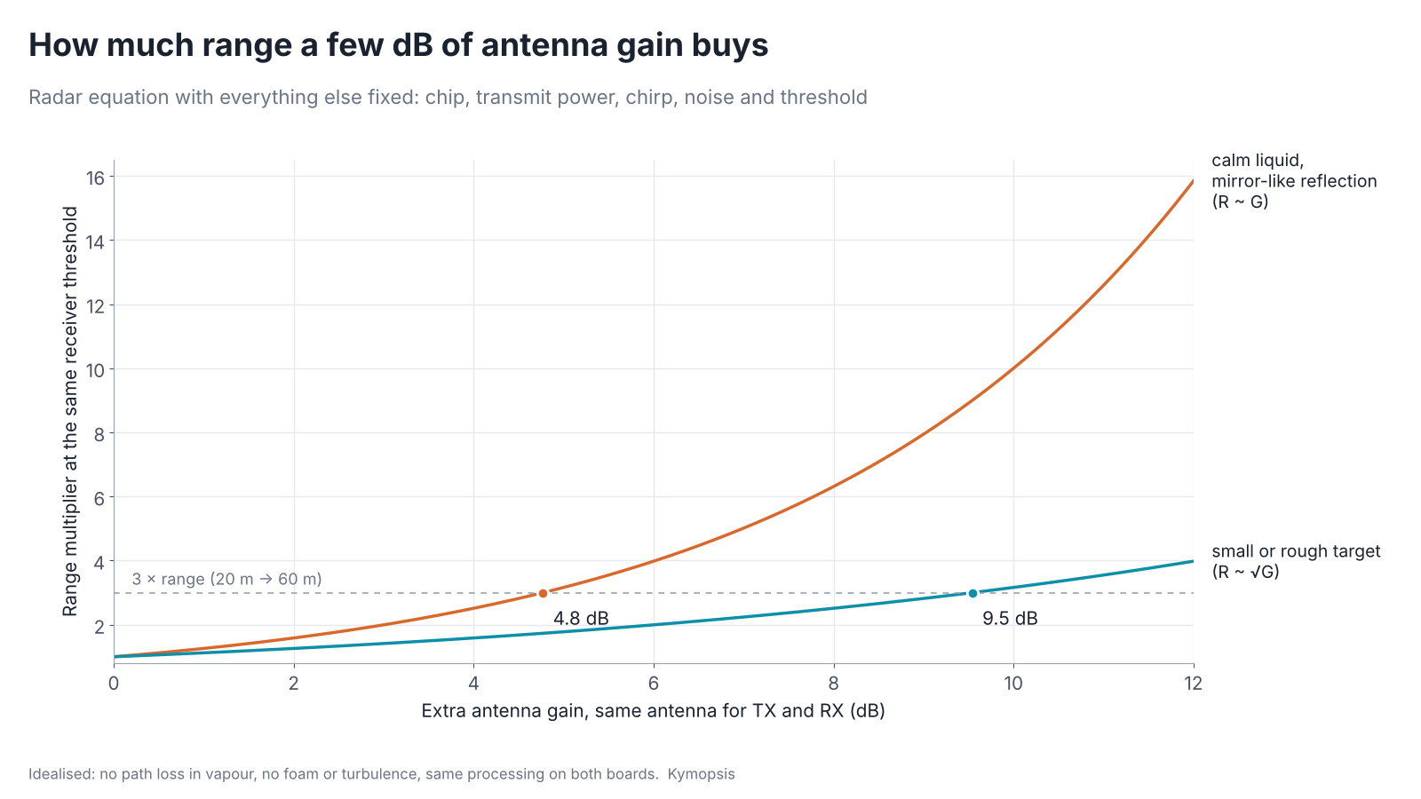
Put together, with the same antenna for both directions and everything else fixed:
- Calm liquid, mirror-like reflection: received power ∝ G²/R², so range grows in proportion to G. Tripling the range needs about 4.8 dB more gain.
- Small or rough target: received power ∝ G²/R⁴, so range grows as √G. Tripling the range needs about 9.5 dB more gain.
A real surface sits somewhere between those two lines. Either way, the losses from Reason 1 and Reason 2 can plausibly add up to the few dB that separate a 20 m sensor from a 60 m one. We have not measured the two boards against each other on a range, so we are not putting a dB figure on the actual difference; the maker states 9 dBi for the bare patch board and no gain for the horn and lens.
Reason 3: a narrow beam keeps the tank walls out of the picture
A floodlight hung in a narrow well lights the walls, the ladder and the pipes as brightly as the water at the bottom; a spotlight lights only the water. A wide antenna beam makes the radar see the tank the way the floodlight does.
Range on a datasheet is usually quoted for a clean target. Inside a tank, the limit is often not the noise floor but the clutter. A wide beam also lights up the ladder, the inlet pipe, an agitator, weld seams and the wall itself, and each of those returns an echo that the radar has to reject. The further down the surface is, the wider the footprint of a given beam, and the more of the tank it sees.


Both boards have false-echo learning in the firmware (full, zone, and remaining zone), which masks echoes that do not move. It helps, but it works best when the fixed echoes are few and weaker than the surface. A narrow beam is what makes that true in a tall vessel. This is also why the 20 m kit ships with its lens radome instead of as a bare board: the lens narrows the beam and the maker rates the board up to 30 m with it.

If you design your own housing, the plastic in front of the antenna matters as much as the lens. Our radome design guide for 24–80 GHz radar covers wall thickness, materials and the near-range reflection a cover adds.
Where the millimetres come from: signal-to-noise and phase
A ruler marked only in centimetres still lets you place a pencil line to about a millimetre, by judging where it falls between two marks. A radar does the same between its range bins, and the phase of the echo, which turns once every 1.9 mm, works like a finer scale laid over the coarse one.
A frequent question is how a radar quotes ±2 mm when its range resolution is centimetres. FMCW range resolution is c/2B. Even if the chip swept the whole 76–81 GHz band, B = 5 GHz gives 3 cm per range bin. Resolution, though, is about telling two targets apart. Accuracy for one strong target, a liquid surface, is a different thing: the firmware can locate the peak far more finely than one bin by interpolating between bins and, in many designs, by reading the phase of the echo, which turns over once every λ/2 ≈ 1.9 mm of distance at 78.5 GHz. The maker does not say which method these boards use.
For a given chip and sweep, both methods get better with signal-to-noise ratio, and with a wider sweep bandwidth. The two kits show the second lever: the 60 m board runs a long-range waveform with a narrower sweep, and on our bench it holds ±4 mm at any distance, against ±2 mm for the 20 m board. So the waveform sets the floor, and the antenna, through SNR, decides whether the reading stays on that floor at the bottom of a tall tank. The full mechanism, with the formulas and the other places it is used, is in our article on FMCW radar phase measurement: sub-millimetre displacement on bridges and slopes, breathing and heartbeat research, and angle finding with several receive channels.
Which board for which job
- Buckets, tanks and sumps a few metres deep: the 20 m board with its lens radome. It is the more accurate one (±2 mm measured), and it is small and easy to mount through a lid.
- Tall silos, wells, open channels and anything past about 20 m: the 60 m board with the horn and lens. The beam stays narrow at range and the stated range covers the job.
- Your own antenna or housing: start from the board that matches your range, and keep transmit and receive on one phase centre if you add a lens.
Both are sold as one product, the 80 GHz radar level sensor kit, with the antenna fitted, a USB-to-TTL adapter and the configuration GUI. They are development kits for engineers and integrators.
Try it yourself: examples/ch04_antenna_aperture.py in the open-source radar-basics-sim repository runs this chapter’s core simulation; change the assumptions and see what moves.
-

80 GHz Radar Level Sensor Development Kit, 76–81 GHz, 20 or 60 Meter Range
From $99.00Reset options60-meter kit, horn + lens20-meter kit, lens radomeSelect options This product has multiple variants. The options may be chosen on the product page -
WR-15 Standard Gain Horn Antenna, 50–75 GHz, 25 dBi
$1,299.00 Buy Now
For integration work beyond a single board, see radar system design and RF antenna design.
FAQ
Why can’t I just put a bigger lens on the 20 m board?
You can, and the maker’s lens radome does take it from 20 m to 30 m. A bigger lens narrows the beam, but at the same focal distance the transmit and receive beams stay the same angle apart, so the split costs more and more of what the lens gains. A shared feed avoids that.
Is the horn and lens version always better?
No. It is longer and heavier, and the 20 m board measures tighter (±2 mm) than the 60 m board (±4 mm, whose long-range waveform uses a narrower sweep). For short ranges the 20 m board is the better fit.
Does the chip have different firmware on each board?
Both run level-measurement firmware with the same UART protocol and settings. The maker does not publish the chirp configuration, so we cannot say whether it differs, and this article does not depend on it.
Can I fit the horn and lens to the 20 m board?
No. The horn bolts over a waveguide launch pad that only the 60 m board has. The 20 m board’s antenna is printed on the PCB.
Sources and method
- C. A. Balanis, Antenna Theory: Analysis and Design, 4th ed., Wiley, 2016 (aperture gain, beamwidth, sidelobes).
- P. F. Goldsmith, Quasioptical Systems: Gaussian Beam Quasioptical Propagation and Applications, IEEE Press, 1998 (Gaussian beams, lens feeds, spillover).
- Module maker’s datasheets for the two 80 GHz level boards (range values quoted in this post). Accuracy values are Kymopsis bench measurements of the two kits.
- Beam and gain figures are computed in Python from the formulas shown (illustrative aperture models, not measurements of the boards).