


An RF attenuator is the simplest part in the box: a few resistors that throw away a fixed fraction of the power and still look like 50 Ω from both ends. That second half is what separates it from a single series resistor, and it is why attenuators turn up everywhere: in front of spectrum analyzers and SDRs, between a signal generator and a mixer, after an amplifier on the bench, and on VNA ports and generator outputs to give a steadier 50 Ω match. An attenuator lowers the power by a set number of decibels while keeping the line matched at 50 Ω. This page explains the decibel arithmetic, what is inside a pad, what it does to reflections, and which numbers on a datasheet matter.
Decibels: why pads are counted in dB
A pad of A dB passes 10−A/10 of the power. The point of decibels is that pads in a row add: a 10 dB pad followed by a 20 dB pad is a 30 dB pad, and the fraction left is 0.1 × 0.01 = 0.001. In dBm, the level after a pad is simply the level before it minus A.
Pout/Pin = 10−A/10 Vout/Vin = 10−A/20
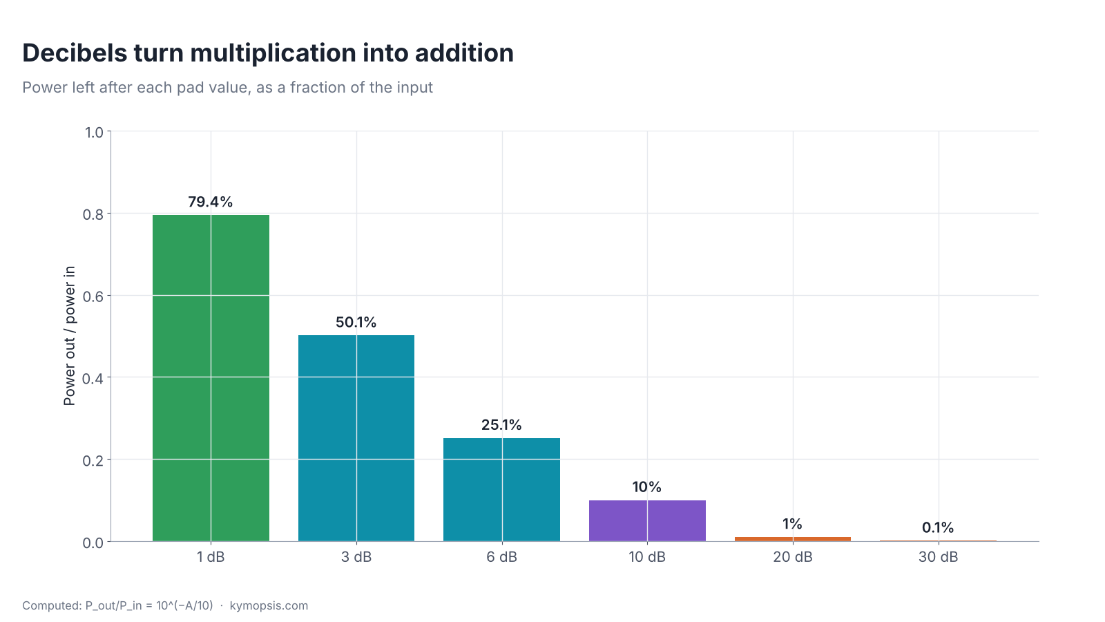
Voltage drops more slowly than power: a 3 dB pad halves the power but leaves 70.8% of the voltage, because power goes with voltage squared. That matters when you read a level on an oscilloscope instead of a spectrum analyzer.
What is inside: pi and T pads
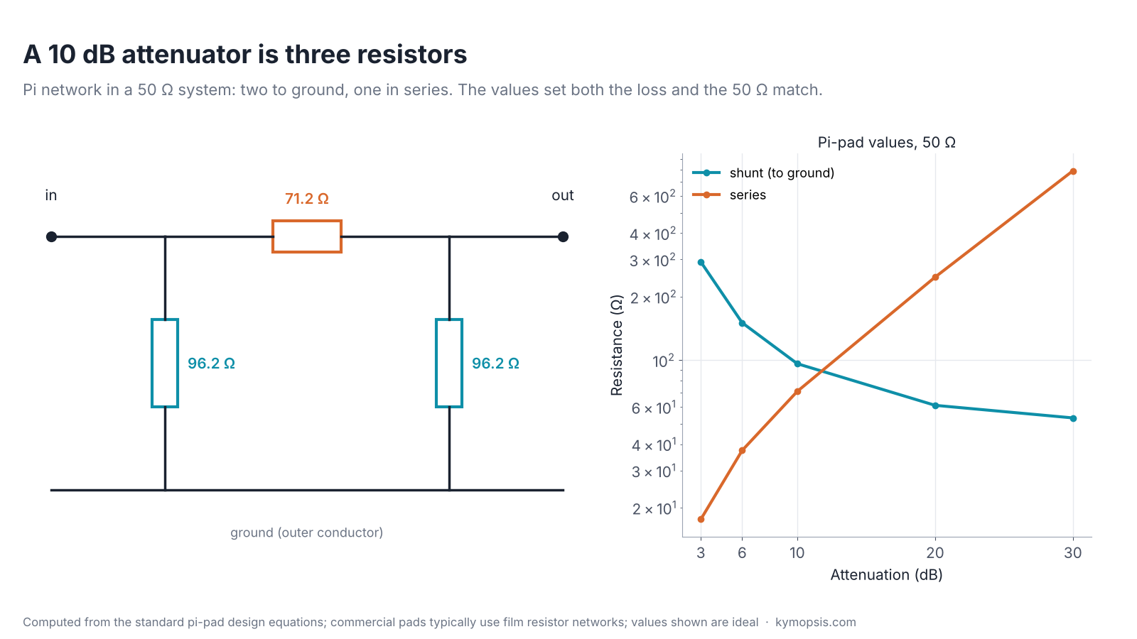
A single series resistor would lower the level, but it would also change the impedance the source sees, so the reflections and the loss would both depend on what is connected. A pad uses resistors to ground as well, chosen so that a 50 Ω load on the output looks like 50 Ω at the input, and the other way round. Two layouts do this. The pi pad has two resistors to ground with one series resistor between them; the T pad has two series resistors with one to ground in the middle. With K = 10A/20 and Z0 = 50 Ω:
Pi: Rshunt = Z0(K+1)/(K−1), Rseries = Z0(K²−1)/(2K)
T: Rseries = Z0(K−1)/(K+1), Rshunt = 2Z0K/(K²−1)
| Pad | Pi shunt (×2) | Pi series | T series (×2) | T shunt |
|---|---|---|---|---|
| 3 dB | 292.4 Ω | 17.6 Ω | 8.5 Ω | 141.9 Ω |
| 6 dB | 150.5 Ω | 37.4 Ω | 16.6 Ω | 66.9 Ω |
| 10 dB | 96.2 Ω | 71.2 Ω | 26.0 Ω | 35.1 Ω |
| 20 dB | 61.1 Ω | 247.5 Ω | 40.9 Ω | 10.1 Ω |
| 30 dB | 53.3 Ω | 789.8 Ω | 46.9 Ω | 3.2 Ω |
Both give the same loss and the same match at 50 Ω; the choice is about which resistor values are practical. Coaxial pads that work to several gigahertz typically use thin- or thick-film resistor networks on a small substrate, laid out so the resistors behave like resistors up to the rated frequency. Through-hole resistors on a board do not, which is why a home-made pad that is fine at 10 MHz is not a guide to what it does at 2.4 GHz.
Check the 10 dB values by hand
K = 1010/20 = 3.162. Pi shunt = 50 × 4.162 / 2.162 = 96.2 Ω; pi series = 50 × (10 − 1) / (2 × 3.162) = 71.2 Ω. Terminate the output in 50 Ω: 96.2 Ω in parallel with 50 Ω is 32.9 Ω, plus 71.2 Ω in series is 104.1 Ω, in parallel with the input shunt 96.2 Ω gives 50.0 Ω. The T version uses 26.0 Ω in each arm and 35.1 Ω to ground.
Where the power goes
Everything the pad does not pass becomes heat in the resistors. A 10 dB pad passes 10%, so with 1 W in it dissipates 0.9 W. That is why attenuators carry an average power rating, usually given at room temperature and lowered (derated) as the temperature rises, plus a separate peak rating for short pulses. The rating that matters is the one for the first pad the signal meets, because it sees the full input power and takes the largest share of the heat (90% if it is a 10 dB pad). Our guide to protecting an analyzer input works through the ratings of the pads we stock.
Pads make a bad match look better
A reflection from whatever is connected to the far side of a pad crosses the pad twice, once out and once back, so an ideal pad of A dB improves the return loss seen at its input by 2A dB. Put a 10 dB pad in front of an open circuit, which reflects everything, and the input sees a return loss of 20 dB, a VSWR of about 1.22. This is why a pad on a signal generator or a mixer port steadies the level: the source sees a reasonable load whatever is on the other end.
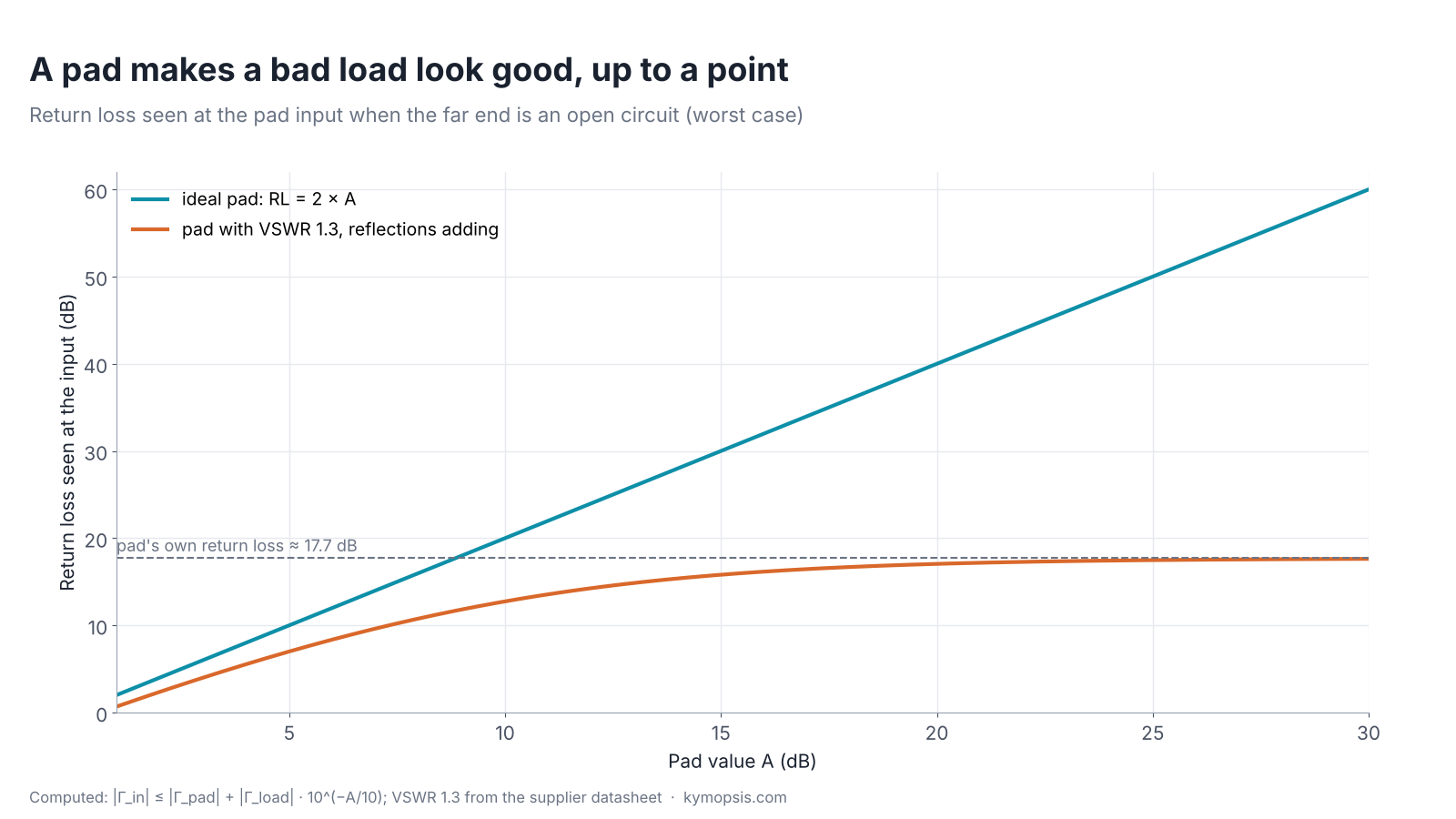
The catch is that the pad has its own reflection. A pad specified at VSWR 1.3 has a return loss of about 17.7 dB by itself. When its reflection and the attenuated reflection from the far end add in phase, the input of a 10 dB pad on an open circuit can show only 12.7 dB, and a 20 dB pad 17.1 dB, instead of 20 and 40 dB. When they cancel, the result is better than the pad alone; the datasheet VSWR is a limit, not a typical value. So a pad helps a badly matched port a lot and a well matched port hardly at all, and when a well-matched load is measured through the pad, the result cannot be more precise than the pad’s own match.
Fixed, step and variable attenuators
- Fixed coaxial pads (SMA, N): one value each, the usual bench part. Stack them for other values.
- Step attenuators: a set of pads switched in by knob or by relay, for changing level without reconnecting.
- Digital step attenuators: chips switched by a microcontroller, common on SDR and transceiver boards.
- Variable (voltage-controlled) attenuators: PIN-diode or similar circuits for automatic level control; their match and linearity change with setting, so they are not a reference.
Reading an attenuator datasheet
| Line on the datasheet | What it tells you |
|---|---|
| Frequency range (for example DC–18 GHz) | where the value, accuracy and VSWR are guaranteed |
| Attenuation and accuracy (±dB) | tolerance of the value; stacked pads add their tolerances, worst case |
| VSWR | the pad’s own reflection, which limits the return-loss improvement above |
| Average power and derating | how much continuous power it takes at a given temperature |
| Peak power and pulse conditions | short pulses only; pulse width and duty cycle must match the datasheet |
| Connector genders | male–female pads go straight onto a port; check the instrument side |
Two things a pad does not do: it does not block DC, which passes through the resistors, and it does not filter. A strong signal outside the band you are looking at is attenuated by the same amount as the one you want. For DC, add a DC block; for an out-of-band signal, add a filter. DC power also counts toward the average power rating.
Pads with other connectors and higher frequency ranges are in the attenuators and terminations section of the RF catalog.
-

SMA RF Fixed Attenuator, DC–18 GHz, 50 Ohm, 1dB to 30dB, Stainless Steel Body, 2W
$35.00Reset options1 dB2 dB3 dB4 dB5 dB6 dB7 dB8 dB9 dB10 dB15 dB20 dB30 dBSelect options This product has multiple variants. The options may be chosen on the product page
FAQ
What does a 10 dB attenuator do?
It passes 10% of the power and turns the other 90% into heat, while still presenting 50 Ω at both ends.
Can I stack attenuators?
Yes. The values add in dB, and so do their tolerances. The first pad sees the full input power, so it must be rated for it; it dissipates the largest share of the heat.
Is a pi pad better than a T pad?
Electrically they give the same loss and match. The layout that suits the resistor values and the frequency range is chosen by the maker.
Does an attenuator block DC?
No. DC passes through the resistors and heats them. Use a DC block if DC can be present.
Why does a pad improve return loss?
A reflection crosses the pad twice, so an ideal A dB pad improves return loss by 2A dB. The pad’s own reflection limits this in practice.
Sources and method
- Supplier datasheet for the DC–18 GHz SMA fixed attenuators we stock: VSWR 1.25, 2 W maximum input, accuracy by value. The VSWR 1.3 pad in the return-loss example is a typical worst case for small SMA pads.
- D. M. Pozar, Microwave Engineering, 4th ed., Wiley, 2012: reflection coefficient, return loss, matched resistive networks.
- ARRL Handbook for Radio Communications: pi and T attenuator design tables.
Resistor values, power fractions and return-loss curves are computed from the formulas shown; nothing here is a measurement.