


Feed one antenna to two receivers, sample a signal for a monitor while it goes on to its load, or add two generators into one test port: all three need a power divider. Two cables twisted onto one T-connector would do the splitting but wreck the match and let the two outputs talk to each other. A power divider splits one signal into equal parts while keeping every port matched to 50 Ω and the outputs isolated from each other; run backwards, the same part is a combiner. This page explains how the common Wilkinson design does that, what the split costs, the catch when combining, and how to read a divider datasheet.
Splitting costs power, by definition
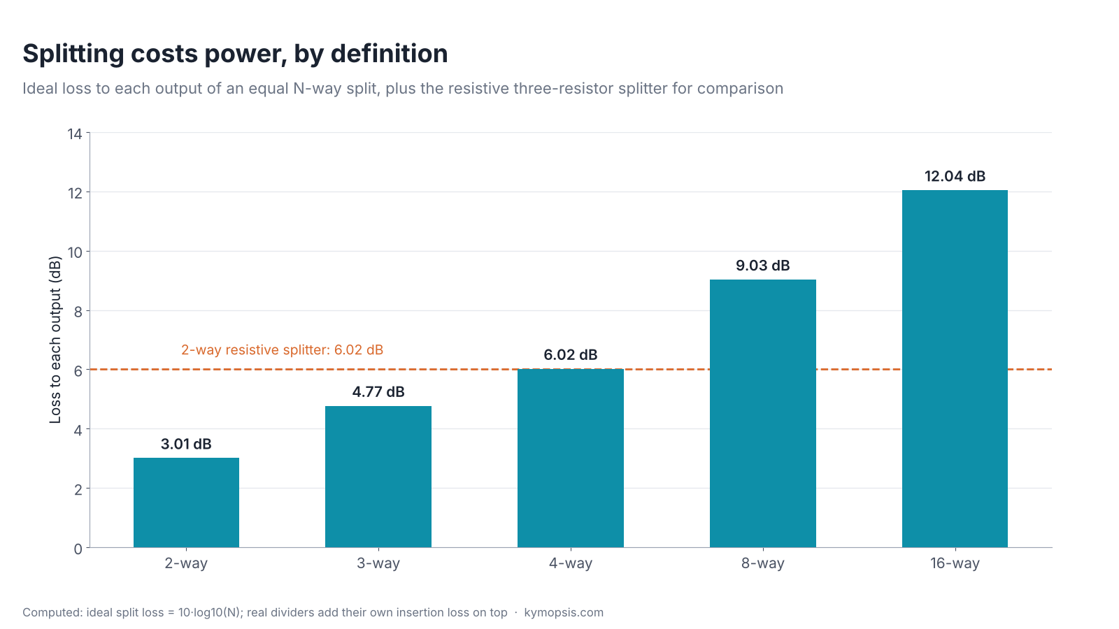
Energy is conserved, so a lossless 2-way divider gives each output half the input: 3.01 dB down. A 4-way divider gives a quarter, 6.02 dB down, and an N-way divider 10·log10N dB: 9.03 dB for 8 ways. A resistive 2-way splitter, covered below, gives 6.02 dB per output because half the power becomes heat. The 3.01 dB of a lossless split is not loss in the sense of heat, it is just sharing: run in reverse with two equal in-phase signals, the same part adds them back. On top of it every real divider has some insertion loss of its own.
How the Wilkinson divider works
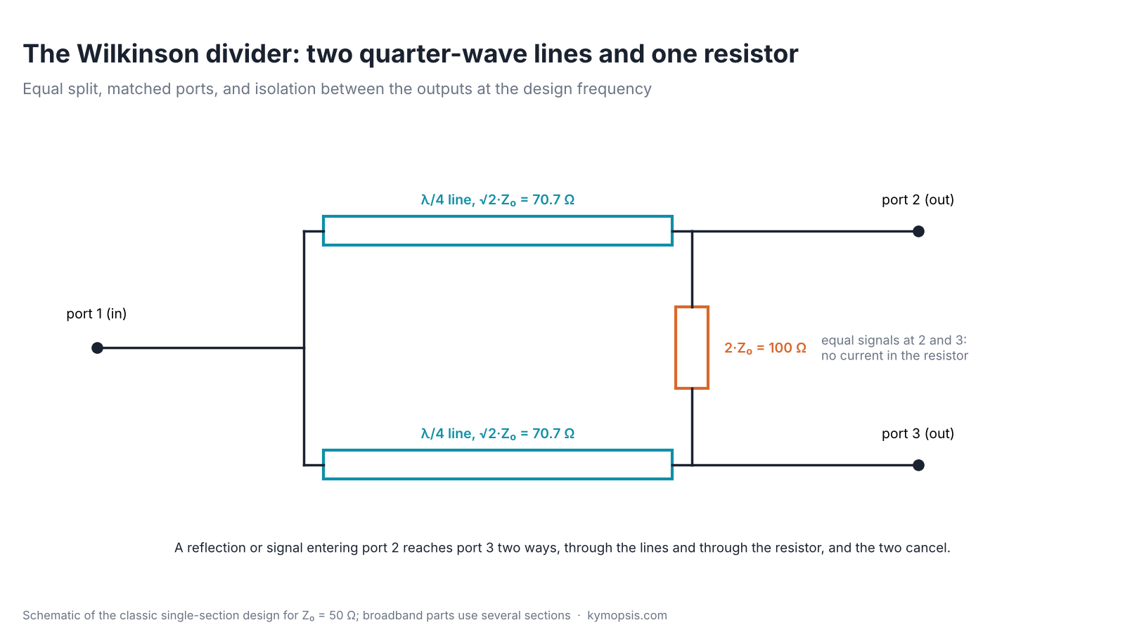
The Wilkinson divider, published by Ernest Wilkinson in 1960, uses two quarter-wavelength lines of √2·Z0, 70.7 Ω in a 50 Ω system, and one resistor of 2·Z0, 100 Ω, across the two outputs. Each quarter-wave line transforms the 50 Ω load on its output into 100 Ω at the input junction; two 100 Ω branches in parallel make 50 Ω, so the input is matched.
When the divider is splitting, both outputs carry identical signals, so both ends of the resistor are at the same voltage and no current flows in it: the resistor costs nothing. It only works when something arrives at one output, a reflection from a mismatched load, for example. That signal reaches the other output by two paths, back through both quarter-wave lines and directly through the resistor, and the two arrive in opposite phase and cancel. That is the isolation. Of the signal that came in at that output, half is absorbed in the resistor and half goes back out of the input port.
Zline = √2·Z0 ≈ 70.7 Ω, R = 2·Z0 = 100 Ω, line length = λ/4
A single quarter-wave section only does all of this near one frequency. Dividers that cover a wide range, like the one we stock, from 0.5 to 6 GHz, are typically built with several sections in a row, and their datasheets give the worst figures over the whole range.
Resistive splitters: the DC-to-daylight alternative
Three 16.7 Ω resistors in a star (Z0/3 each) also make a 50 Ω 2-way splitter. It works from DC upward because nothing in it depends on wavelength, but each output is 6.02 dB below the input instead of 3.01 dB, the other half of the power becomes heat, and the two outputs are only 6 dB apart from each other. It is the right choice for broadband signal monitoring, and the wrong one when you need isolation or power.
Using it as a combiner
Run backwards, a divider adds two signals into one port. Two equal signals that arrive in phase add completely: 1 W plus 1 W gives 2 W at the output and nothing in the resistor. In opposite phase they cancel at the output and all 2 W goes into the resistor. Two signals at different frequencies, the usual case when combining two generators for an intermodulation test, split half and half on average. The curve assumes equal amplitudes; unequal inputs put some power in the resistor even in phase.
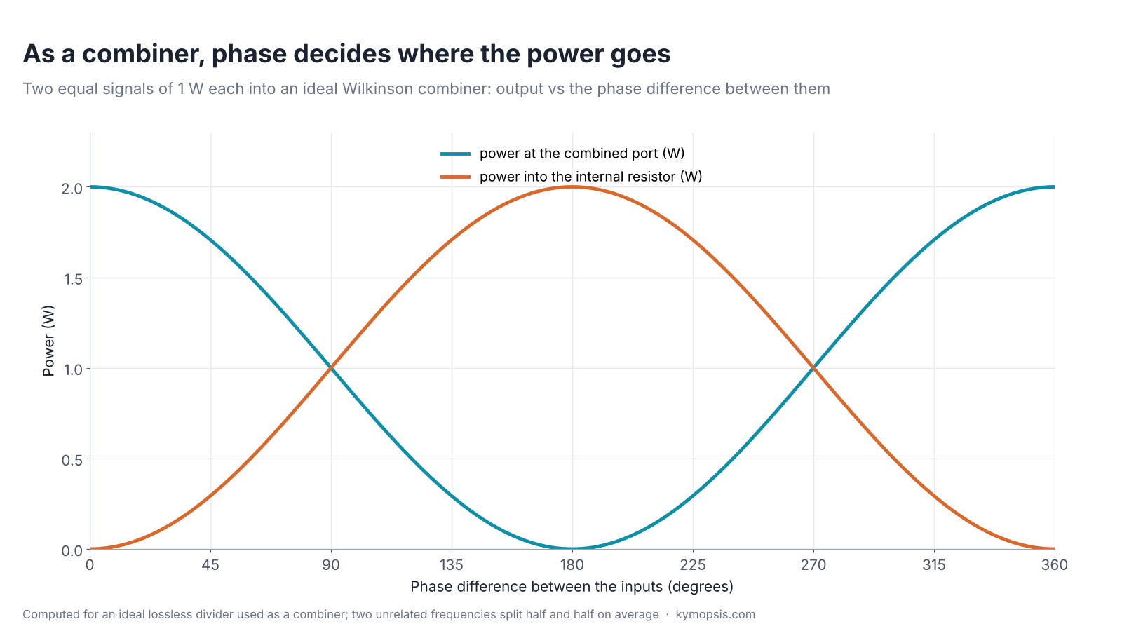
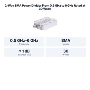
So the power rating that matters for combining is the internal resistor’s, not the divider’s. The datasheet of the divider we stock gives 30 W CW, which is a rating for the divider; it does not list a separate figure for combining. When combining anything stronger than bench signal levels, ask for the combiner rating first.
Reading a divider datasheet
| Line | 2-way SMA divider we stock | What it means |
|---|---|---|
| Frequency range | 0.5–6 GHz | where all the limits below apply |
| Insertion loss | ≤ 1.0 dB | loss of the part itself, on top of the 3 dB split |
| Amplitude balance | ± 0.2 dB | how equal the two outputs are |
| Phase balance | ± 2° | how equal their phase is; matters for antenna arrays and I/Q work |
| Isolation | ≥ 18 dB | how much of a signal at one output reaches the other |
| VSWR | ≤ 1.4 | match of the ports; return loss ≥ 15.6 dB |
| Power | 30 W CW | continuous power as a divider |
| Connectors, temperature | SMA female, -35 to +75 °C | add SMA male cables |
Divider datasheets give insertion loss on top of the 3.01 dB split, and the one we stock says so explicitly: each path loses at most about 4.0 dB (3.01 dB split plus 1.0 dB). Port match is explained in our VSWR and return loss explainer.
Practical tips
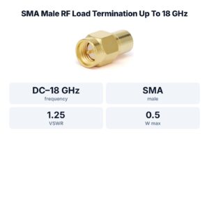
- Terminate unused outputs with a 50 Ω load. An open output reflects its share: the other output only sees that reflection at the isolation level, but about a quarter of the input power comes back out of the input (VSWR about 3) and another quarter heats the internal resistor.
- Isolation is finite: with 18 dB, a signal at one output appears 18 dB down at the other. For two receivers on one antenna that is usually fine; for a transmitter and a receiver it is not.
- Stay inside the rated band. Below 0.5 GHz the quarter-wave sections are electrically too short, and match and isolation fall off.
- For level setting after the split, use attenuators; our attenuator explainer covers the arithmetic.
Dividers with more outputs or for other bands are in the dividers and bias tees section of the RF catalog.
Formula sheet
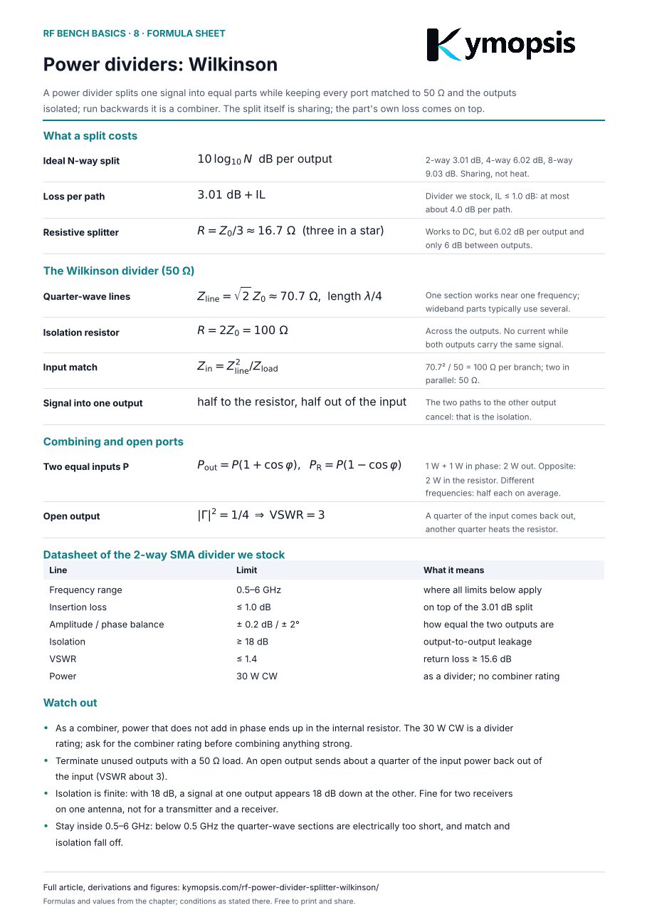
Every formula and key number from this page on one A4 sheet, to print or keep next to the bench: download the formula sheet (PDF, 1 page). Free to print and share.
FAQ
What is the difference between a splitter and a divider?
Usage varies between makers; what matters is whether it is resistive (broadband, 6 dB, little isolation) or a Wilkinson-type divider (3 dB, isolated outputs).
Why does a 2-way divider lose 3 dB?
Each output gets half the power, which is 3.01 dB. That is sharing, not heat; the part’s own insertion loss comes on top.
Can I use a power divider as a combiner?
Yes, it is reciprocal. But power that does not add in phase is dissipated in the internal resistor, so check the combiner rating before combining anything strong.
Can I connect two receivers to one antenna?
Yes, through a 2-way divider. Each receiver sees about 3 dB less signal, plus the divider’s own loss.
Why does the resistor matter if no current flows in it?
It only carries current when the two outputs differ, for example from a reflection. That is what isolates the outputs.
Sources and method
- Supplier datasheet for the 2-way SMA power divider we stock: 0.5–6 GHz, insertion loss max 1.0 dB, amplitude balance ±0.2 dB, phase balance ±2°, VSWR 1.4, isolation min 18 dB, 30 W CW, SMA female, -35 to +75 °C.
- E. J. Wilkinson, “An N-Way Hybrid Power Divider,” IRE Transactions on Microwave Theory and Techniques, 1960.
- D. M. Pozar, Microwave Engineering, 4th ed., Wiley, 2012: Wilkinson divider, resistive divider.
Split losses and combiner curves are computed for ideal parts; product figures are from the datasheet.